Power amplifier power controller

a power amplifier and power controller technology, applied in the direction of gain control, high-frequency amplifiers, modulation, etc., can solve the problems of reducing the maximum transmit power, stressing the pa, and distortion of adjacent channel leakage, so as to reduce the maximum transmit power of the power amplifier is rapidly optimized, and the input drive level constant

Active Publication Date: 2014-05-20
QUANTANCE
View PDF10 Cites 31 Cited by
  • Summary
  • Abstract
  • Description
  • Claims
  • Application Information

AI Technical Summary

Benefits of technology

[0009]Embodiments of the present invention include a power amplifier system that is configured to adjust the gain of a power amplifier based on one or more sensed operating conditions of the power amplifier while maintaining substantially constant a level of the input signal to the power amplifier. A power amplifier power controller in the power amplifier system monitors various operating conditions of the power amplifier, and controls the output transmit power by coordinated control of both the input drive to the power amplifier and the gain of the power amplifier. Thus, the transmit power is maximized within the constraints of the operating conditions. The power amplifier power controller receives the monitored operating conditions of the power amplifier, and then controls the input drive level to the power amplifier so that the input drive level does not change while adjusting the gain of the power amplifier to maximize the transmit power. Thus, the power amplifier power controller may be added to the power amplifier system without interfering with the normal operation of the power amplifier system.
[0011]In another embodiment, the power amplifier power controller may adjust the input drive level by some portion of the overall change required to the power of the power amplifier rather than maintaining the input drive level constant, while adjusting the gain of the power amplifier by the remaining portion of the overall change required to the power of the power amplifier. As a result, less gain adjustment range is required in the power amplifier
[0012]The power amplifier system according to the embodiments herein has the advantage that it can locally monitor the operating conditions of the power amplifier and respond by autonomously and rapidly optimizing the maximum transmit power of the power amplifier by adjusting the gain of the power amplifier while maintaining substantially constant the input drive level to the power amplifier. Thus, the power amplifier controller can be added to existing TXIC systems without interfering with their operation.

Problems solved by technology

Further, the mobile device may reduce the maximum transmit power if the PA cannot meet transmit adjacent channel leakage limit specifications as required by standards such as 3 Gpp TS 25.101.
Such power reduction may be required if challenging peak to average (PAR) in the modulation, impedance mismatch conditions at the antenna (due to the antenna being placed in proximity to a metal surface, for example), temperature changes or other factors cause the PA to operate in a nonlinear mode, resulting in distortion which generates adjacent channel leakage.
Finally, it may be prudent to monitor and limit the maximum current drawn from the PA, since for some impedance mismatch angles at the antenna, the PA may draw excessive current, stressing the PA or reducing battery life of the mobile device.
However, the conventional RF PA system typically cannot accurately limit the maximum transmit power of the RF output signal 115 based on the criteria mentioned earlier.
For example, when the PA 104 drives a load (not shown) at an unexpected impedance due to an impedance mismatch at the antenna, increased adjacent channel leakage typically occurs.
However, TXIC 102 will sense forward power 113 at directional coupler 112 which is somewhat unpredicted, due to the directional coupler's lack of 50 Ohms operating environment.
The mobile device's maximum transmit power is thus reduced beyond what is needed, detrimentally affecting mobile phone coverage and data rates.
Additionally, the feedback loop operates at a slow rate, since the forward power 113 of the RF signal detected at directional coupler 112 must be heavily averaged to accurately assess the forward power level, causing a large delay in adjustment of the mobile device's maximum transmit power level, during which time the mobile device's maximum transmit power is not optimized.

Method used


Image

  • Power amplifier power controller
  • Power amplifier power controller
  • Power amplifier power controller

Examples


Embodiment Construction

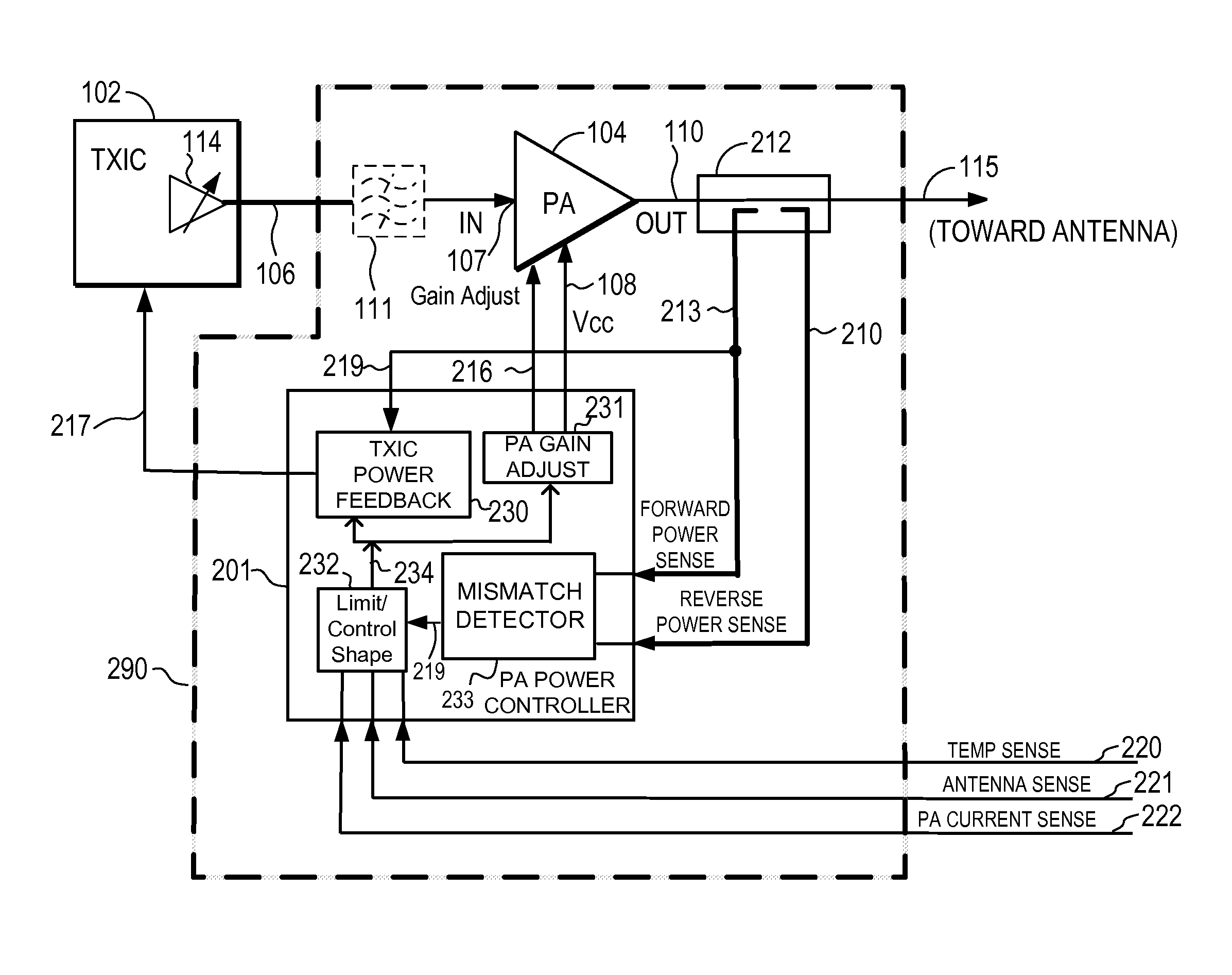
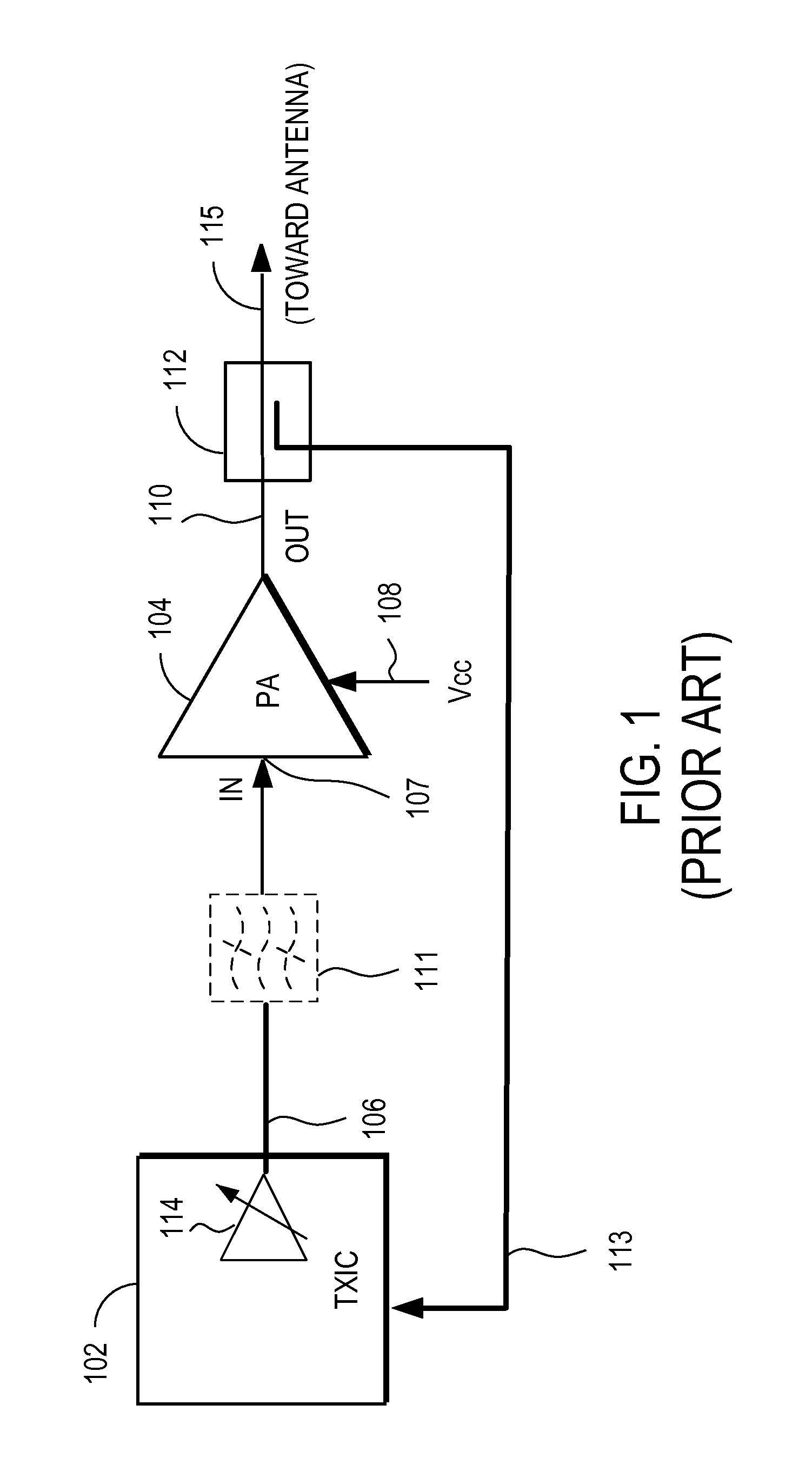
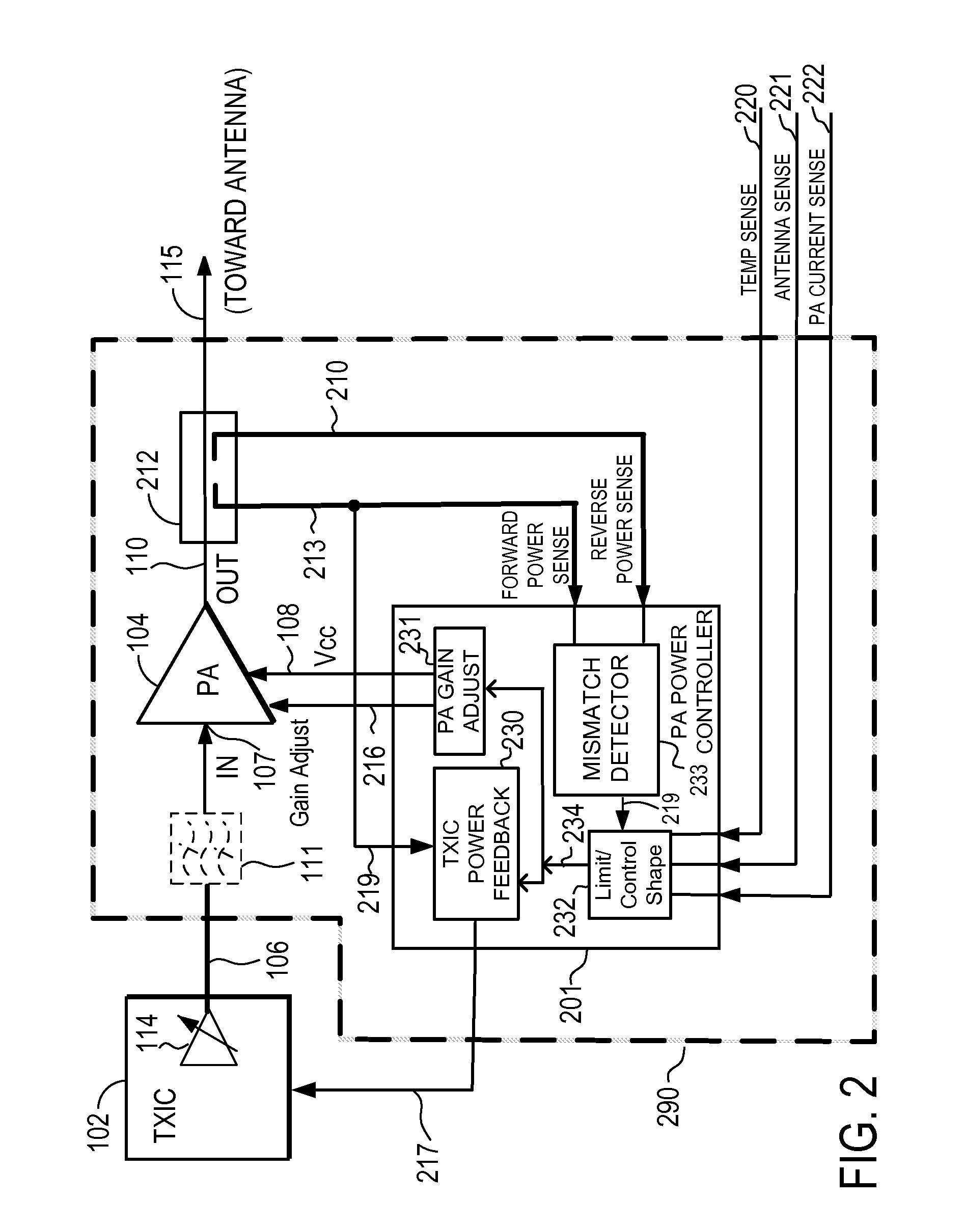
[0017]The figures and the following description relate to preferred embodiments of the present invention by way of illustration only. It should be noted that from the following discussion, alternative embodiments of the structures and methods disclosed herein will be readily recognized as viable alternatives that may be employed without departing from the principles of the present invention.

[0018]Reference will now be made in detail to several embodiments of the present invention(s), examples of which are illustrated in the accompanying figures. It is noted that wherever practicable similar or like reference numbers may be used in the figures and may indicate similar or like functionality. The figures depict embodiments of the present invention for purposes of illustration only. One skilled in the art will readily recognize from the following description that alternative embodiments of the structures and methods illustrated herein may be employed without departing from the principle...


PUM


Abstract

A power amplifier power controller in the power amplifier system monitors various operating conditions of the power amplifier, and controls the output transmit power of the power amplifier by coordinated control of both the input drive level to the power amplifier and the gain of the power amplifier. The power amplifier power controller controls the input drive level to the power amplifier so that the input drive level does not change substantially while adjusting the gain of the power amplifier to maximize the transmit power. The power amplifier power controller may also adjust the input drive level by some portion of the overall change required to the power of the power amplifier, while adjusting the gain of the power amplifier by the remaining portion of such overall change.

Description

BACKGROUND OF THE INVENTION[0001]1. Field of the Invention[0002]This invention relates to power amplifier systems.[0003]2. Description of the Related Art[0004]RF power amplifiers (PA's) are widely used in the transmitter section of radio transceivers, such as in cellular phones and data cards used with mobile computing devices. The PA provides the last amplification stage for the RF signal being transmitted by the antenna.[0005]In cellular telephone systems, the power delivered by the PA and consequently transmitted by the antenna is typically controlled in a closed loop fashion, where the basestation commands the mobile device to transmit at a proper power level in order to maintain a good communication link to the basestation. As the mobile moves farther away from the basestation, the basestation commands the mobile device to increase its transmit power until a maximum transmit power limit is reached as determined by the mobile device. This maximum transmit power is determined by ...

Claims


Application Information

Patent Timeline
Patent Type & Authority Patents(United States)
IPC IPC(8): H04B1/04
CPCH03F3/20H03F3/189H03F2200/207H03F2200/204H03G3/20H03G3/3042H03F3/24H03F2200/465
Inventor DROGI, SERGE FRANCOISTOMASZ, MARTINVINAYAK, VIKAS
Owner QUANTANCE
Why Eureka
Try Eureka