Inhalation device and heating unit therefor
a technology of inhalation device and heating unit, which is applied in the direction of inhalators, other medical devices, tobacco, etc., can solve the problems of complicated technical measures, insufficient stability of flames in combustion chambers, and significant differences in the handling of known inhalation devices
- Summary
- Abstract
- Description
- Claims
- Application Information
AI Technical Summary
Benefits of technology
Problems solved by technology
Method used
Image
Examples
first embodiment
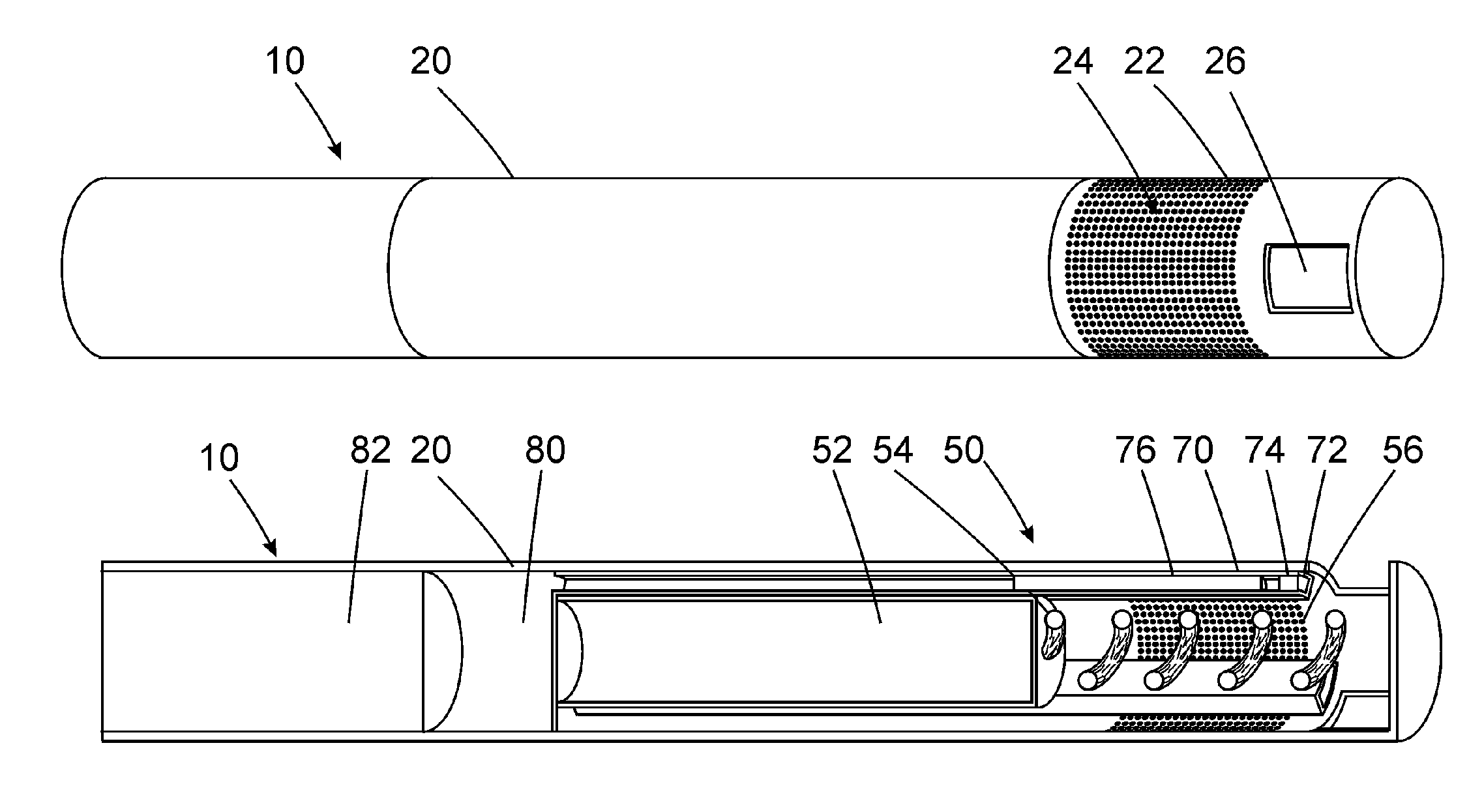
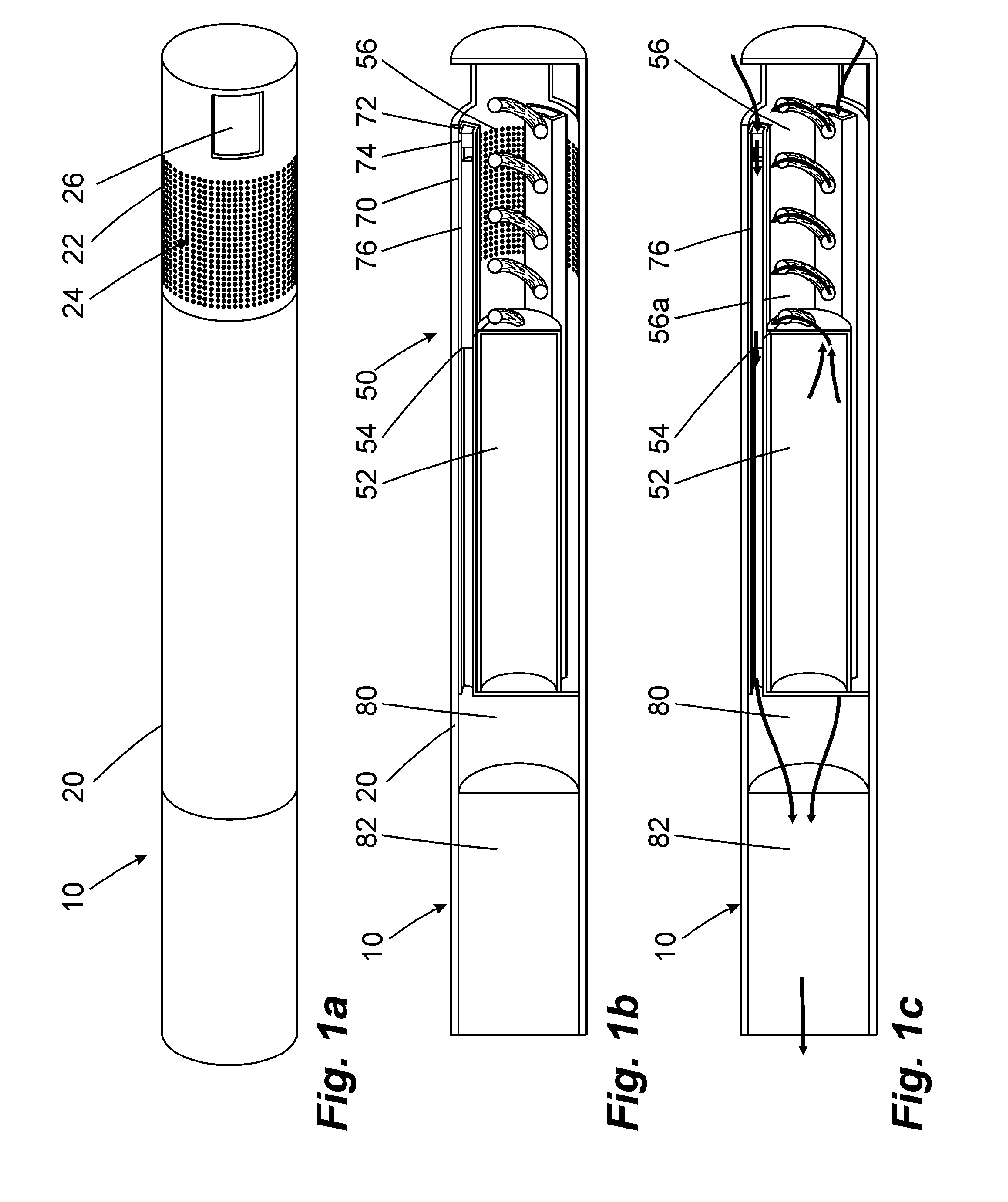
[0058]FIGS. 1a to 1c show an inventive inhalation device 10. It is of cylindrical design and has an outside wall 20 that is provided with micro openings 24 at a distal end of the inhalation device 10 as combustion chamber wall 22. The wall 20 has a recess 26 at the distal end face.
[0059]FIG. 1b shows the inside construction of the inhalation device 10. A heating unit 50 is provided at the distal end of the inhalation device 10. The heating unit has a fuel storage 52 in which the fuel is stored in a liquid state. A wick 54 extends from the fuel storage 52 into a combustion chamber 56 that is provided at the distal end of the inhalation device and that is surrounded by the combustion chamber wall 22. The wick 54 is formed like a screw. A total of three inhalation mixture generators 70 are arranged on an inside of the outside wall 20 distributed over the circumference and each extends essentially axially starting from the distal end of the inhalation device in the direction of the prox...
second embodiment
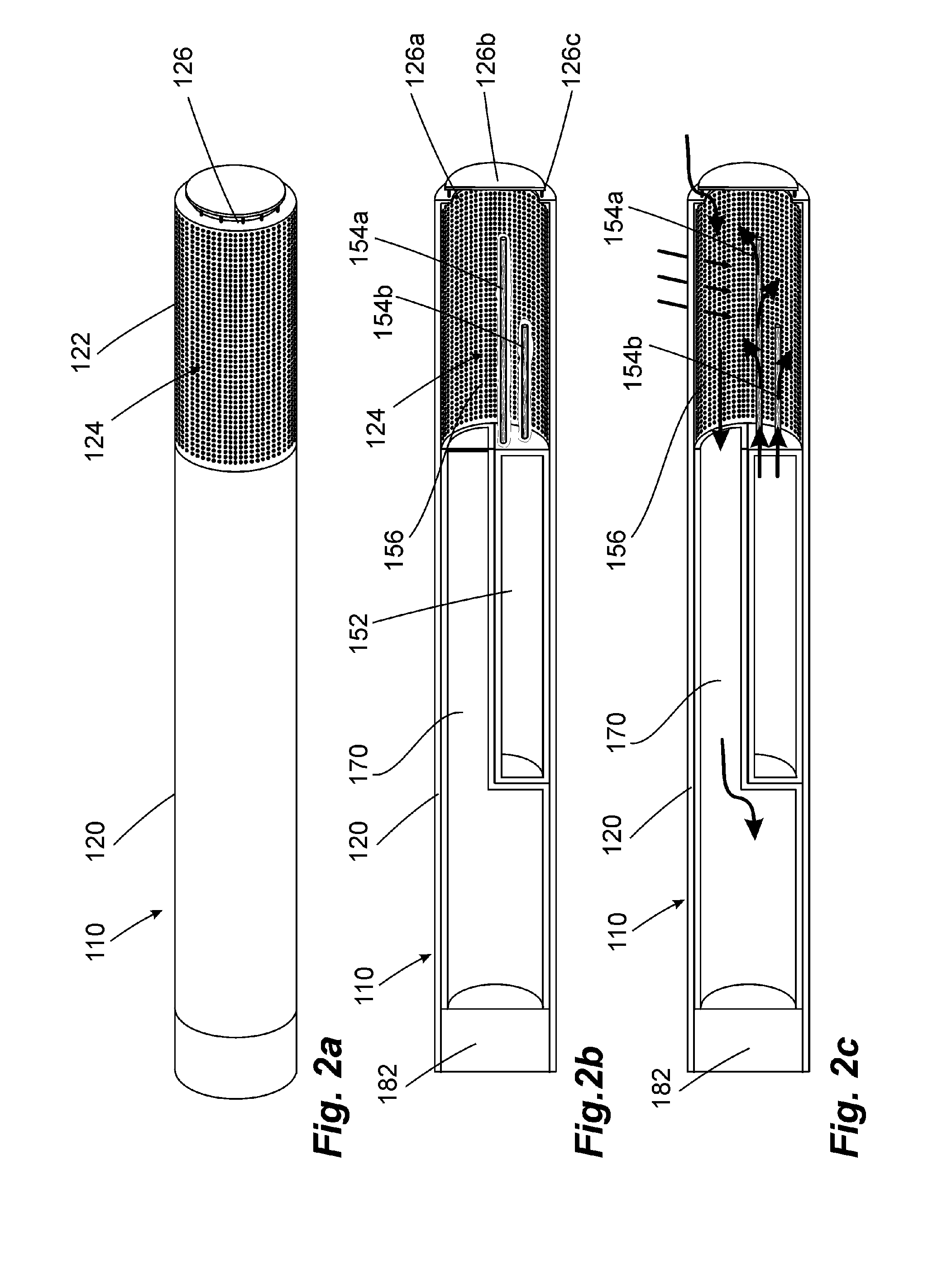
[0064]FIGS. 2a to 2c show an inventive inhalation device. In many regards this inhalation device 110 is similar to the embodiment of FIG. 1. If nothing else is specified below, its method of operation is the same.
[0065]The inhalation device 110 exhibits an outside wall 120 whose front end is designed as combustion chamber wall 122. A fuel storage 152, a combustion chamber 156, and an inhalation mixture generator 170 are provided inside this outside wall 120.
[0066]The arrangement of the inhalation mixture generator 170 and of the fuel storage 152 deviates from the embodiments of FIG. 1. While the inhalation mixture generator 170 occupies the entire cross section in the rear area of the inhalation device 110, the cross section splits into two semi-circular cross sectional areas in the central area of the inhalation mixture generator 170, the one being occupied by the fuel storage 152 and the other by the inhalation mixture generator 170. This simplified design is advantageous with reg...
third embodiment
[0071]A third embodiment can be gathered from FIGS. 3a to 3c. The inhalation device 210 that has been illustrated has a cylindrical shape with a jacket shaped outside wall 220. It is closed at the distal end by a cup shaped fuel storage 252 of chromium-nickel spring steel, the fuel storage 252 containing a fuel 258 of a gel-like consistency and being open in the direction of a combustion chamber 256. Before starting the inhalation device 210, the open side of the fuel storage 252 is closed, as can be seen in FIG. 3b, by a membrane 260 made from a material of low elasticity, for example an aluminum foil.
[0072]The combustion chamber 256 is surrounded by micro openings 224 in a combustion chamber wall section 222 of the outside wall 220. An ignition access 226 is additionally provided on one side and comprises a total of four elongate apertures between which only narrow webs are provided. An inhalation mixture generator 270 adjoins the combustion chamber 256 on the proximal side and is...
PUM
 Abstract
Description
Claims
Application Information
 - R&D
- Intellectual Property
- Life Sciences
- Materials
- Tech Scout
- Unparalleled Data Quality
- Higher Quality Content
- 60% Fewer Hallucinations
Browse by: Latest US Patents, China's latest patents, Technical Efficacy Thesaurus, Application Domain, Technology Topic, Popular Technical Reports.
© 2025 PatSnap. All rights reserved.Legal|Privacy policy|Modern Slavery Act Transparency Statement|Sitemap|About US| Contact US: help@patsnap.com


