Brake disc ventilated

a technology for brake discs and discs, which is applied to brake discs, fluid actuated brakes, braking elements, etc., can solve the problems of insufficient heat dissipation, insufficient ventilation of the discs achieved by the prior art, and insufficient heat dissipation of the disc itself, so as to achieve optimal heat dissipation and reduce the mass of the dis

Active Publication Date: 2014-05-27
FRENI BREMBO SPA
View PDF13 Cites 20 Cited by
  • Summary
  • Abstract
  • Description
  • Claims
  • Application Information

AI Technical Summary

Benefits of technology

[0014]In particular, the task of the present invention is to make available a brake disc which guarantees ventilation and therefore optimal heat dissipation and at the same time a reduction of the mass of the disc itself.

Problems solved by technology

Such discs of the prior art are not without defects.
It has in fact been noted that the ventilation of the disc achieved by the discs of the prior art is not optimal and that the consequent dissipation of heat is not fully efficient.
Such scarce dissipation efficiency is due essentially to the width and shape of the connection elements which identify and delimit the internal ventilation channels: such connection elements do not allow optimal air flow.
The solutions of the prior art do not permit the contemporary optimisation of ventilation efficiency with a reduction in mass of the discs.

Method used


Image

  • Brake disc ventilated
  • Brake disc ventilated
  • Brake disc ventilated

Examples


Embodiment Construction

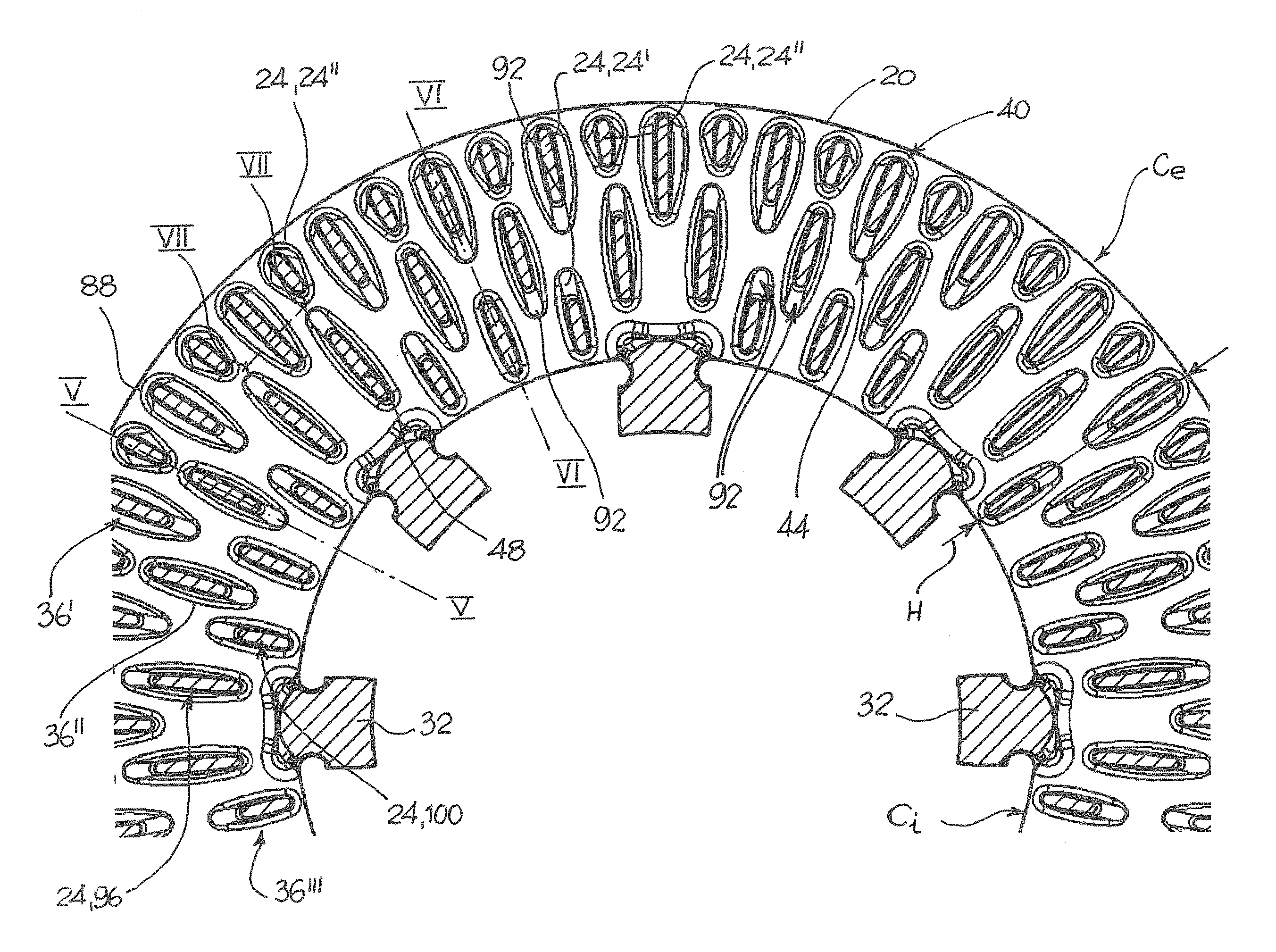
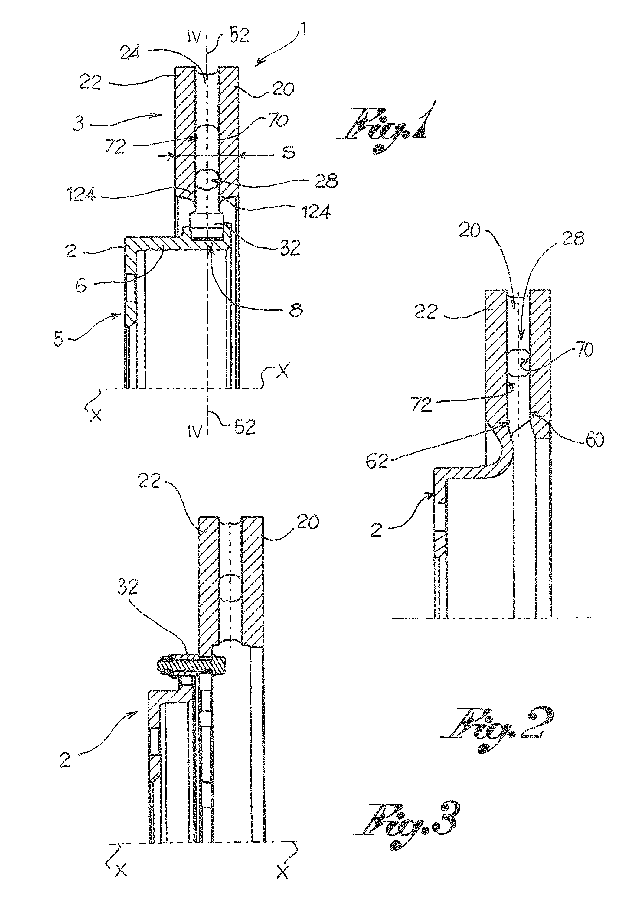
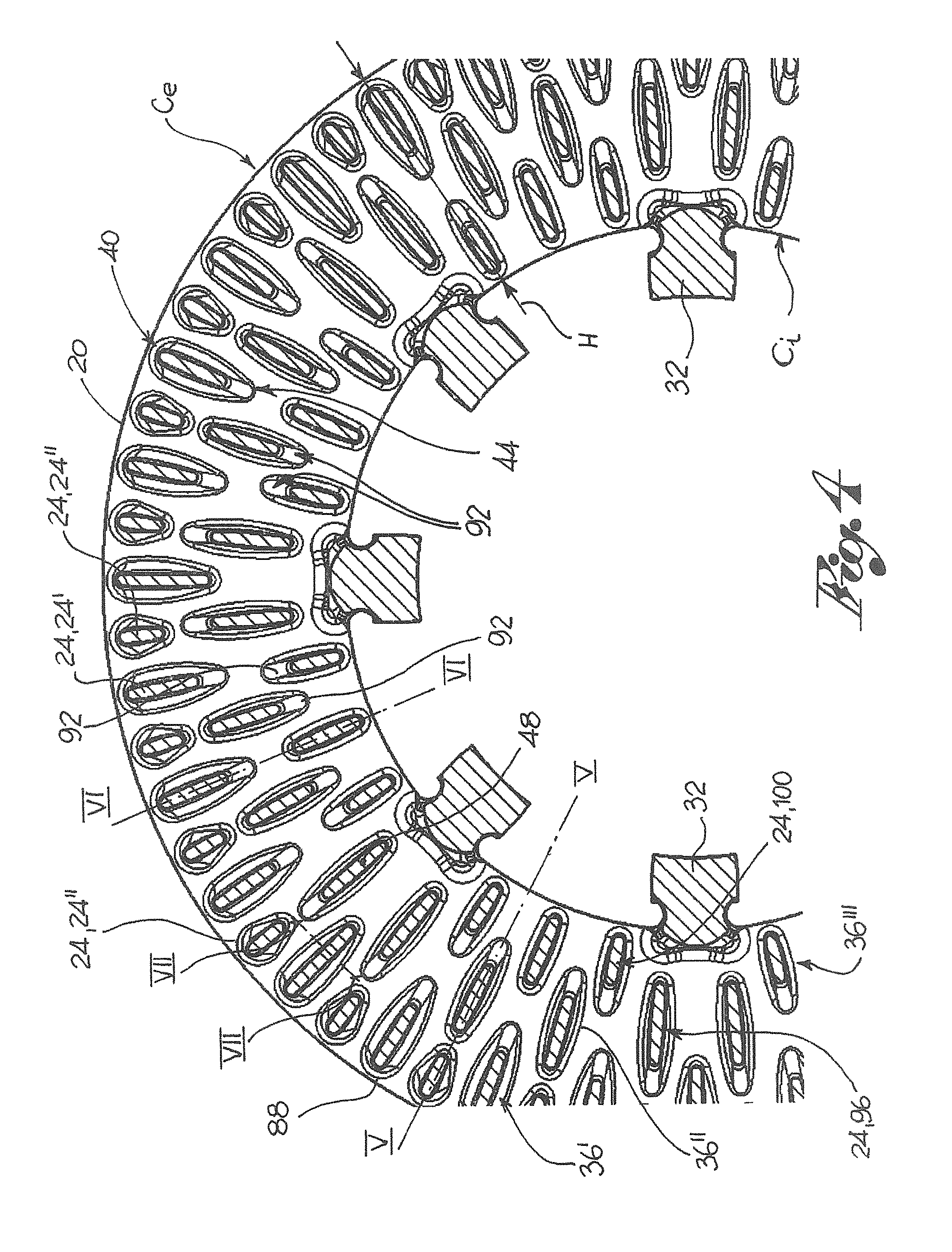
[0026]With reference to the aforesaid figures, reference numeral 1 globally denotes a brake disc according to the invention.

[0027]The brake disc 1 according to the invention comprises two parts which share a rotation axis X. A first inner part, the support carrier 2, is destined to be coupled to the wheel hub of a vehicle, while the remaining peripheral part, the braking band 3, is destined to co-operate with the associable calliper of the brake disc positioned astride the brake disc 1 to exert a braking effect on the vehicle.

[0028]The support carrier 2 comprises a central portion 5 destined to be coupled, for example in a conventional manner, to the wheel hub of a vehicle and a peripheral annular portion 6 which juts out and overhangs the central portion 5, for example in a direction substantially parallel to the rotation axis X-X of the brake disc.

[0029]The support carrier 2 comprises radial seats 8 made in the peripheral annular portion 6.

[0030]The braking band 3 comprises an ann...


PUM


Abstract

A brake disc of a rotation axis, comprising a support carrier, a braking band comprising two flanges connected by a plurality of connection elements which define ventilation channels for the braking band, at least one drive element able to connect the support carrier and the braking band to each other. The connection elements have a variable resistant section in an axial direction parallel to the rotation axis, the resistant section being measured in an area substantially parallel to the direction of the air flow inside the ventilation channels. Such resistant section progressively increasing as it moves from a median resistant section towards the respective connection resistant sections of the connection element to the flanges.

Description

CROSS-REFERENCE TO RELATED APPLICATIONS[0001]This application is a 371 U.S. National Stage of International Application No. PCT / B2010 / 053311, filed Jul. 20, 2010. This application claims the benefit of Italian Patent Application No. PD2009A000240, filed Aug. 7, 2009. The disclosures of the above applications are incorporated herein by reference.FIELD OF THE INVENTION[0002]The present invention relates to a brake disc for vehicles, in particular for motor vehicles.BACKGROUND OF THE INVENTION[0003]Brakes in general and disc brakes in particular, are able to slow down and / or stop the vehicle, transforming kinetic energy into heat energy by means of friction between the disc and pads. For such reason, to keep the brakes efficient, it is important not to overheat the disc and the pads. It is therefore important to achieve efficient heat dissipation into the environment.[0004]To such purpose brake discs are known of comprising a pair of flanges placed side by side which comprise in turn e...

Claims


Application Information

Patent Timeline
Patent Type & Authority Patents(United States)
IPC IPC(8): F16D65/10
CPCF16D65/128F16D2065/1328
Inventor TIRONI, GIOVANNI MARIOBIONDO, SIMONEMEDICI, STEFANODONATI, MICHELE
Owner FRENI BREMBO SPA
Why Eureka
Try Eureka