Device for clearing mucus from the pulmonary system

a pulmonary system and mucus technology, applied in the field of pneumatic pressure stimulation, can solve the problems of consuming and discomforting therapy, and reducing the success of only limited treatment, so as to reduce physical stress to the body, improve the effect of pulmonary system mucus removal, and loosen the mucus attached

Inactive Publication Date: 2014-05-27
IGNAGNI MARIO BATTISTE
View PDF30 Cites 10 Cited by
  • Summary
  • Abstract
  • Description
  • Claims
  • Application Information

AI Technical Summary

Benefits of technology

[0007]A first controllable excitation source applies vibrational stimulations directly to the thorax which, in turn, causes the pulmonary system to develop small-amplitude sympathetic vibrations, thereby loosening the mucus attached to the lungs and trachea. A second independently controllable excitation source applies compressive stimulations to the patient just below the rib cage, leading to upward thrusts of the thoracic diaphragm. Since the lungs rest directly on the thoracic diaphragm, localized motions of the lung walls will be initiated at the points of contact. This causes the air in the lungs to experience pressure and flow-rate pulsations which, in turn, cause the mucus attached to the lungs and trachea to be propelled in incremental steps toward the mouth. Control means are provided to insure that efficacious pulmonary system vibration and thoracic compressions are achieved without undue stress to the patient. The use of two separately controllable thoracic excitation sources offers greater potential for optimization than a single excitation, as applied by existing high-frequency chest compression techniques, and may have advantages in size, cost, mucus clearance rate, and reduced physical stress to the body.

Problems solved by technology

A number of diseases can lead to severe impairment of normal lung functioning.
In all of these diseases, mucus retained in the lungs becomes a natural breeding ground for harmful bacteria that can cause repeated bouts of serious infections, as well as leading to decreased respiratory gas exchange.
This can be a time consuming and discomforting therapy which meets with only limited success, especially if the patient is in a weakened condition.

Method used


Image

  • Device for clearing mucus from the pulmonary system
  • Device for clearing mucus from the pulmonary system
  • Device for clearing mucus from the pulmonary system

Examples


Embodiment Construction

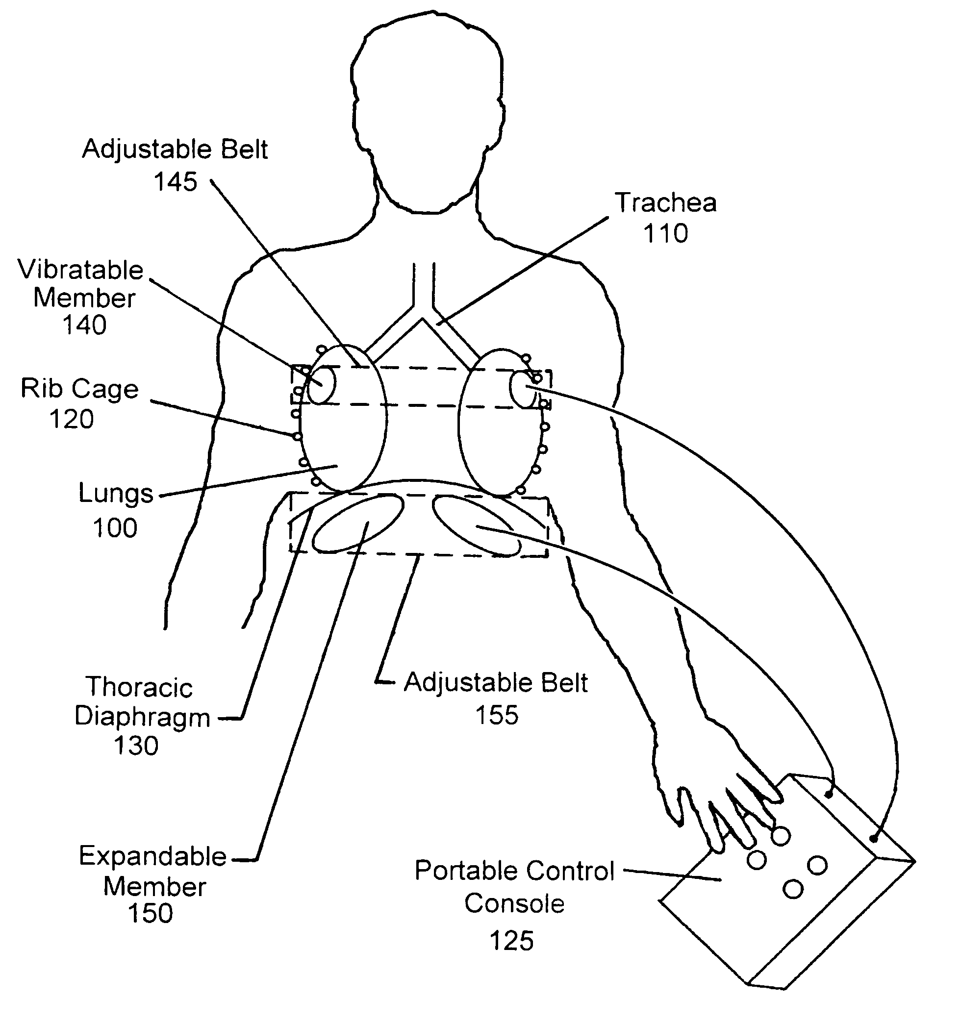
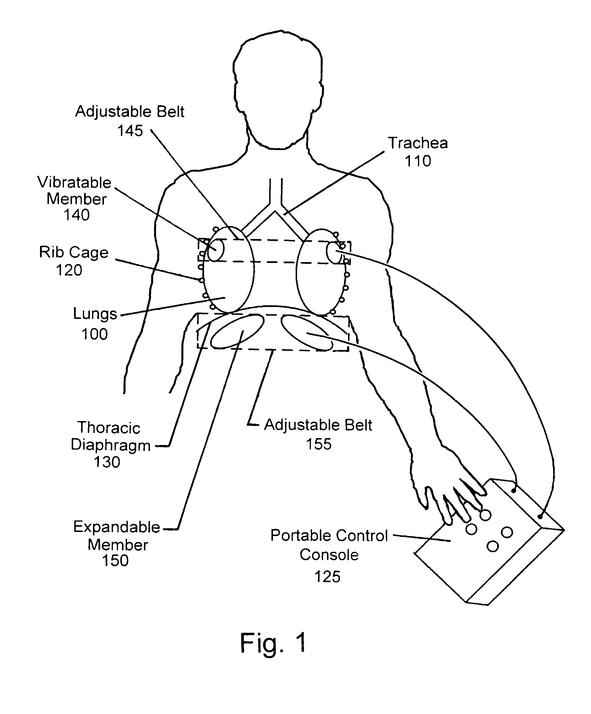
[0013]FIG. 1 illustrates the concept for clearing the lungs 100 and trachea 110 of mucus. The concept is based on the employment of two separately controllable excitations, in combination, to maximize the effectiveness of mucus clearance from the pulmonary system. The first excitation augments the action of the cilia by inducing sustained low-amplitude high-frequency vibrations in the lungs 100. This serves to create continuous oscillatory translational motions of the lung wall relative to the mucus which, in turn, expedites movement of the mucus. Vibration of the lung walls is achieved by employing at least one vibratable member 140 held in contact with the thorax. From a physical perspective, the lung wall behaves essentially like a perfect elastic membrane, while the mucus does not. Accordingly, because the lung wall and mucus respond differently in a vibrational environment, relative motion will occur between them, which creates a boundary layer of lower viscosity mucus adjacent...


PUM


Abstract

A device is disclosed for generating controlled pneumatic pressure to a human body to achieve mucus clearance from the pulmonary system. Controlled pneumatic pressure consisting of individual vibratory pressure and constrictive pressure variations are generated and applied to the thorax to promote mucus clearance. The vibratory pressure variation is channeled to a pressure receiver secured to the upper thorax of the body, and the constrictive pressure variation is channeled to a pressure receiver secured to the lower thorax of the body. The vibratory pressure variation serves to loosen the mucus, while the constrictive pressure variation provides the motive force that promotes mucus expulsion from the pulmonary system.

Description

CROSS REFERENCE TO PRIOR APPLICATION[0001]This application is a continuation-in-part of U.S. patent application Ser. No. 11 / 803,257, entitled “Means For Clearing Mucus From the Pulmonary System”, filed May 14, 2007, now U.S. Pat. No. 7,927,293 B1, issued Apr. 19, 2011, and U.S. patent application Ser. No. 12 / 319,169 “Apparatus for Clearing Mucus From the Pulmonary System”, now U.S. Pat. No. 8,273,039, issued Sep. 25, 2012.FIELD OF THE INVENTION[0002]The invention generally relates to the use of pneumatic pressure stimulations to the human body in promoting clearance of mucus from the lungs and trachea, or to achieve other potential therapeutic benefits.BACKGROUND OF THE INVENTION[0003]A number of diseases can lead to severe impairment of normal lung functioning. Among these are: Cystic Fibrosis, Emphysema, and Immotile Cilia Syndrome. Cystic Fibrosis is a hereditary disease that leads to the accumulation of large quantities of viscous mucus in the lungs. Emphysema causes impairment ...

Claims


Application Information

Patent Timeline
Patent Type & Authority Patents(United States)
IPC IPC(8): A61H1/00A61H7/00A61H9/00
CPCA61H23/0263A61H9/0078A61H2205/08A61H2201/1246A61H2201/0176A61H2201/123A61H2201/165A61H2201/50A61H2201/5071
Inventor IGNAGNI, MARIO, BATTISTE
Owner IGNAGNI MARIO BATTISTE
Why Eureka
Try Eureka