Dynamoelectric device and method of forming the same

a technology of dynamoelectric devices and windings, which is applied in the direction of dynamo-electric components, winding heads, windings, etc., can solve the problems of inefficiency of solid core wire windings in some cases, inefficient solid core wire windings at carrying high frequency alternating current, etc., and achieve compact and efficient end-turn configuration

Inactive Publication Date: 2014-05-27
TRUSTEES OF THE ALICE ANHEUSER BEIMS MOORE IRREVOCABLE TRUST 1 & THE ALICE ANHEUSER BEIMS MOORE IRREVOCALBE TRUST 2 FBO GRANDCHILDREN
View PDF22 Cites 10 Cited by
  • Summary
  • Abstract
  • Description
  • Claims
  • Application Information

AI Technical Summary

Problems solved by technology

However, solid-core wire is inefficient at carrying high frequency alternating current due to skin effects and proximity effects.
Thus, solid core wire windings in some cases can be inefficient.

Method used


Image

  • Dynamoelectric device and method of forming the same
  • Dynamoelectric device and method of forming the same
  • Dynamoelectric device and method of forming the same

Examples


Embodiment Construction

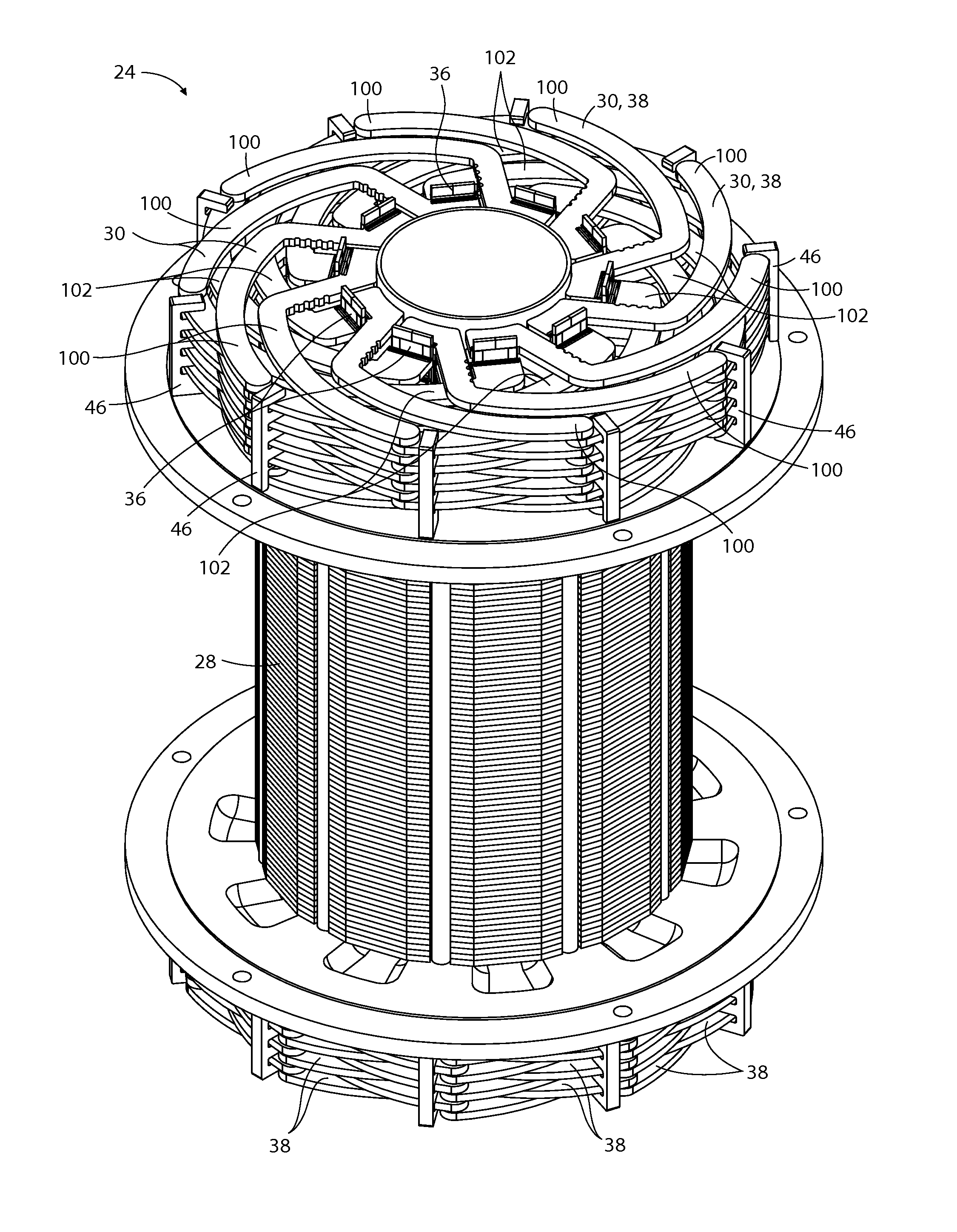
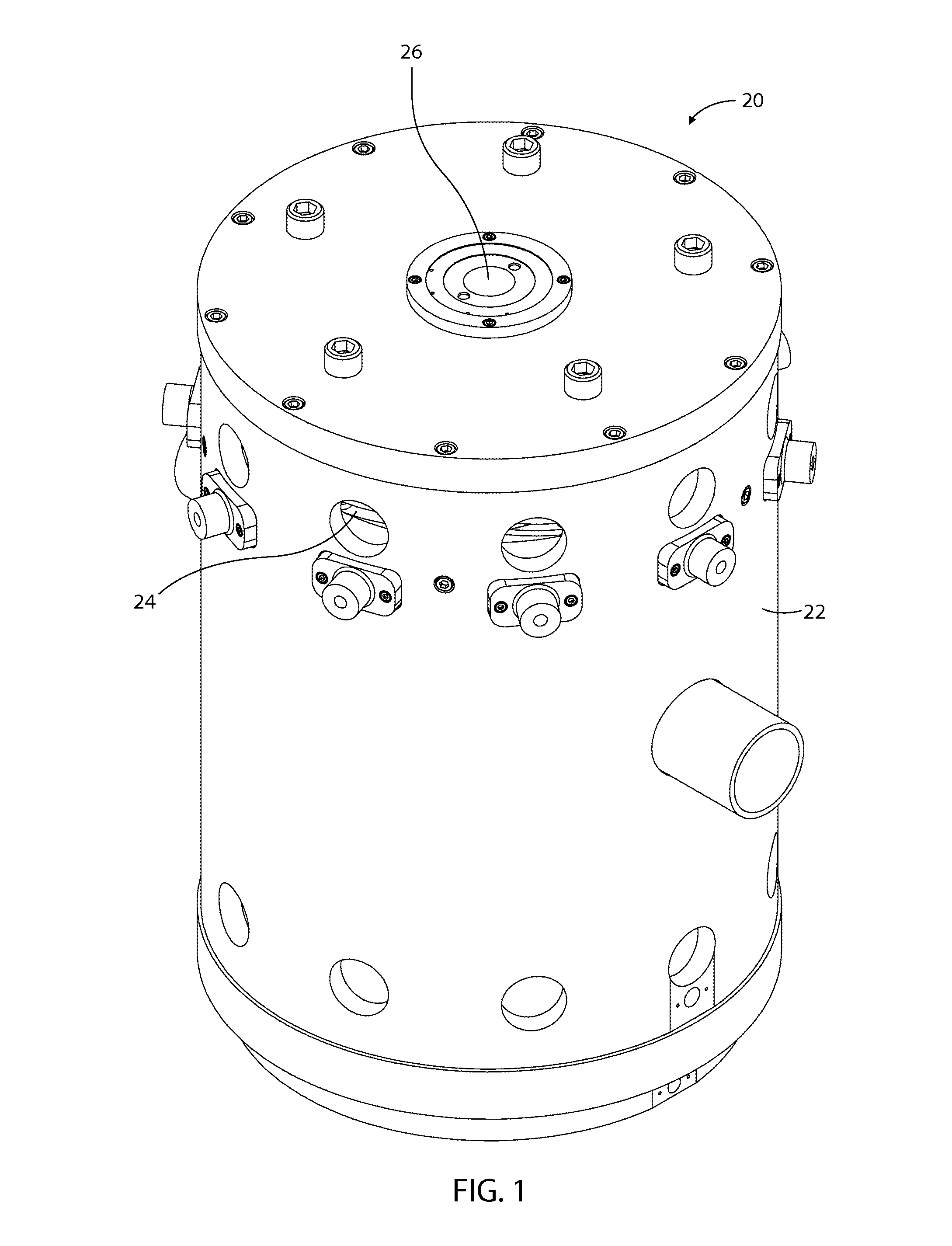
[0021]A dynamoelectric device in accordance with the invention is shown in FIG. 1. This particular dynamoelectric device 20 is configured to function as a generator. The dynamoelectric device 20 comprises a housing 22 that surrounds the stator 24 and the rotor 26. The rotor 26 is preferably a cylindrical body having magnetic poles formed by permanent magnets. The magnets are preferably formed of a rare-earth metal.

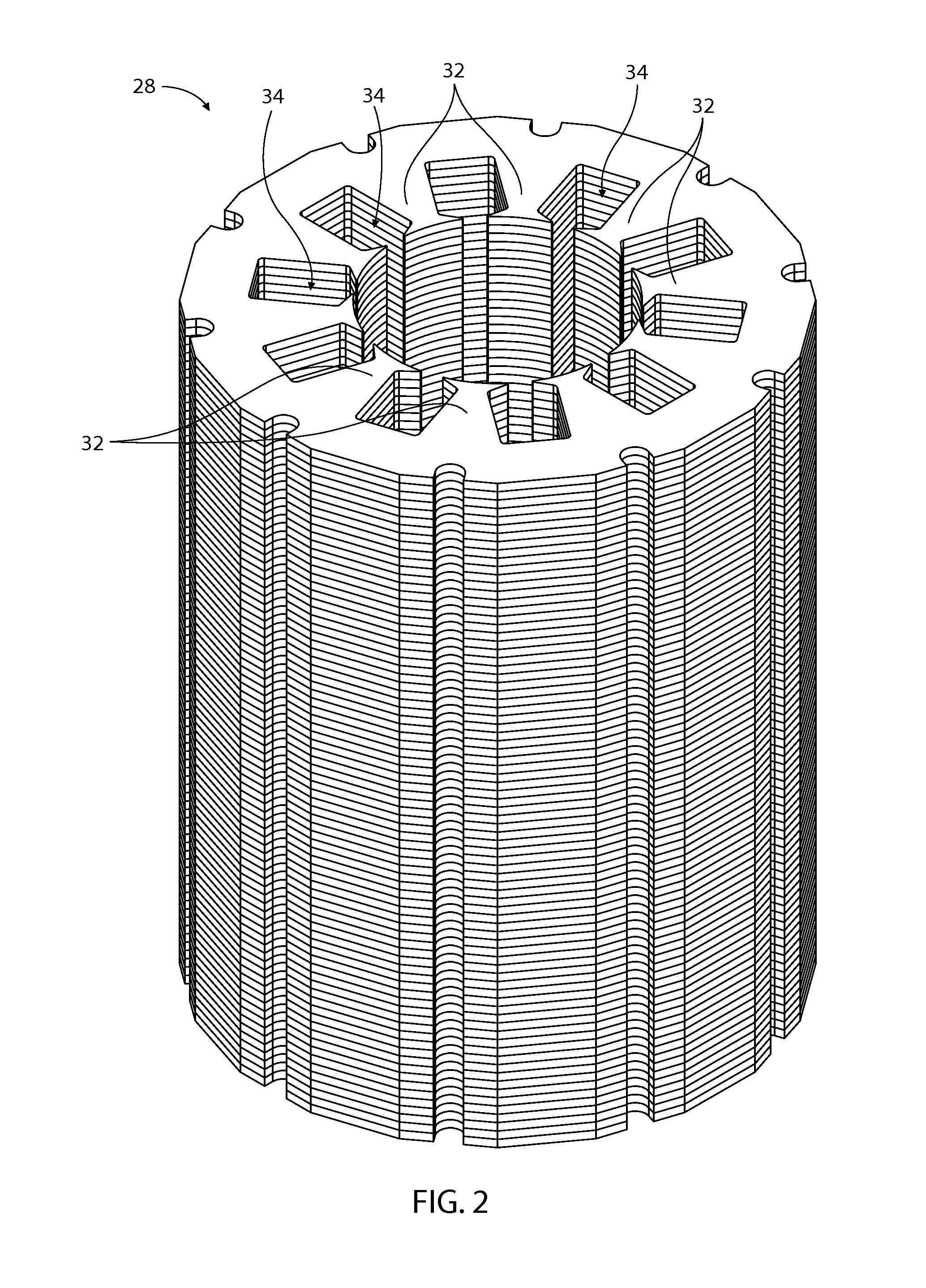
[0022]The stator 24 of the dynamoelectric device 20 comprises a stack of laminates 28 and a plurality of coils 30. The laminates are configured in a manner that forms a plurality of armatures 32 that are circumferentially spaced about an axis and that protrude radially inward toward the axis. As such, a slot 34 is formed between each adjacent pair of the armatures 32. The coils 30 extend axially through these slots 34. Preferably there are ten armatures 32 and five seperate coils 30.

[0023]The five coils 30 are preferably generally identical to each other. One of the coils ...


PUM

PropertyMeasurementUnit
electrically conductiveaaaaaaaaaa
volumeaaaaaaaaaa
volumesaaaaaaaaaa

Abstract

A dynamoelectric device comprises a plurality of armatures arranged circumferentially about an axis, sets of electrically conductive winding members that extend axially through the stack of laminates and are positioned circumferentially between each adjacent pair of the armatures, and first and second layers of end-turn members. Each of the end-turn members of the first axial layer is connected to one of the winding members. Each of the end-turn members of the first axial layer extends clockwise circumferentially from its respective one of the winding members. Each of the end-turn members of the second axial layer is connected to one of the winding members and to each of the end-turn members of the first axial layer of end-turn members. Each of the end-turn members of the second axial layer extends counter-clockwise circumferentially from its respective one of the winding members. The winding members are each formed of Litz wire.

Description

CROSS-REFERENCE TO RELATED APPLICATIONS[0001]None.STATEMENT REGARDING FEDERALLY SPONSORED RESEARCH OR DEVELOPMENT[0002]Not Applicable.APPENDIX[0003]Not Applicable.BACKGROUND OF THE INVENTION[0004]1. Field of the Invention[0005]This invention pertains to dynamoelectric devices. More particularly, the present invention pertains to a unique configuration and method of forming the end-turns and windings of the coils of a dynamoelectric device.[0006]2. General Background[0007]Dynamoelectric electric devices, such as generators, alternators, and motors, typically comprise coils (also frequently called windings) that conduct electricity between adjacent armatures of either the stator or rotor. The electrical current conducted through the coils is typically looped back between another adjacent pair of armatures via what are commonly referred to as end-turns. While the current running through the end-turns can have positive contributions to the magnetic flux fields of a dynamoelectric device...

Claims


Application Information

Patent Timeline
Patent Type & Authority Patents(United States)
IPC IPC(8): H02K3/12
CPCH02K3/12H02K3/50H02K3/42Y10T29/49009
Inventor SCHLOTE, ANDREW
Owner TRUSTEES OF THE ALICE ANHEUSER BEIMS MOORE IRREVOCABLE TRUST 1 & THE ALICE ANHEUSER BEIMS MOORE IRREVOCALBE TRUST 2 FBO GRANDCHILDREN
Why Eureka
Try Eureka