Magnetic field sensor and associated method that can establish a measured threshold value and that can store the measured threshold value in a memory device

a technology of magnetic field sensor and threshold value, which is applied in the direction of instruments, liquid/fluent solid measurement, heat measurement, etc., can solve the problems of inability to accurately determine the positive output of field sensors, inability to provide accurate outputs of field sensors, and inability to provide accurate outputs of positives

Active Publication Date: 2014-05-27
ALLEGRO MICROSYSTEMS INC
View PDF18 Cites 22 Cited by
  • Summary
  • Abstract
  • Description
  • Claims
  • Application Information

AI Technical Summary

Problems solved by technology

Many types of magnetic field sensors do not provide an accurate output signal (e.g., indication of absolute angle of rotation of an object) immediately upon power up of the magnetic field sensor, and / or immediately upon movement of the target object from zero rotating speed, and / or upon movement slowing to zero rotating speed, but instead provide an accurate output signal only once the magnetic field sensor has been powered up for a period of time, and the target object has moved through a substantial rotation or is moving with substantial speed.
However, the outputs of the PDAC and the NDAC may not provide accurate indications of the positive and negative peaks of the magnetic field signal until several cycles of the signal (i.e., signal peaks) occur (i.e., until several gear teeth have passed).
The TPOS detector can provide information to the engine control processor that can be more accurate than information provided by the running mode detector nearly immediately upon power up of the magnetic field sensor and for time periods near the beginning and end of rotation of the target object (e.g., start and stop of the engine and camshaft), but which may be less accurate than the output signal provided by a running mode detector at some time after the magnetic field sensor has powered up and when the object is rotating at speed.
When the magnetic field signal is compared against a fixed predetermined threshold, the changes in the amplitude of the magnetic field signal due to temperature, air gap, etc., can cause undesirable changes in positions of the edges in the above-described output signal from the TPOS detector.

Method used


Image

  • Magnetic field sensor and associated method that can establish a measured threshold value and that can store the measured threshold value in a memory device
  • Magnetic field sensor and associated method that can establish a measured threshold value and that can store the measured threshold value in a memory device
  • Magnetic field sensor and associated method that can establish a measured threshold value and that can store the measured threshold value in a memory device

Examples


Embodiment Construction

[0033]Before describing the present invention, some introductory concepts and terminology are explained.

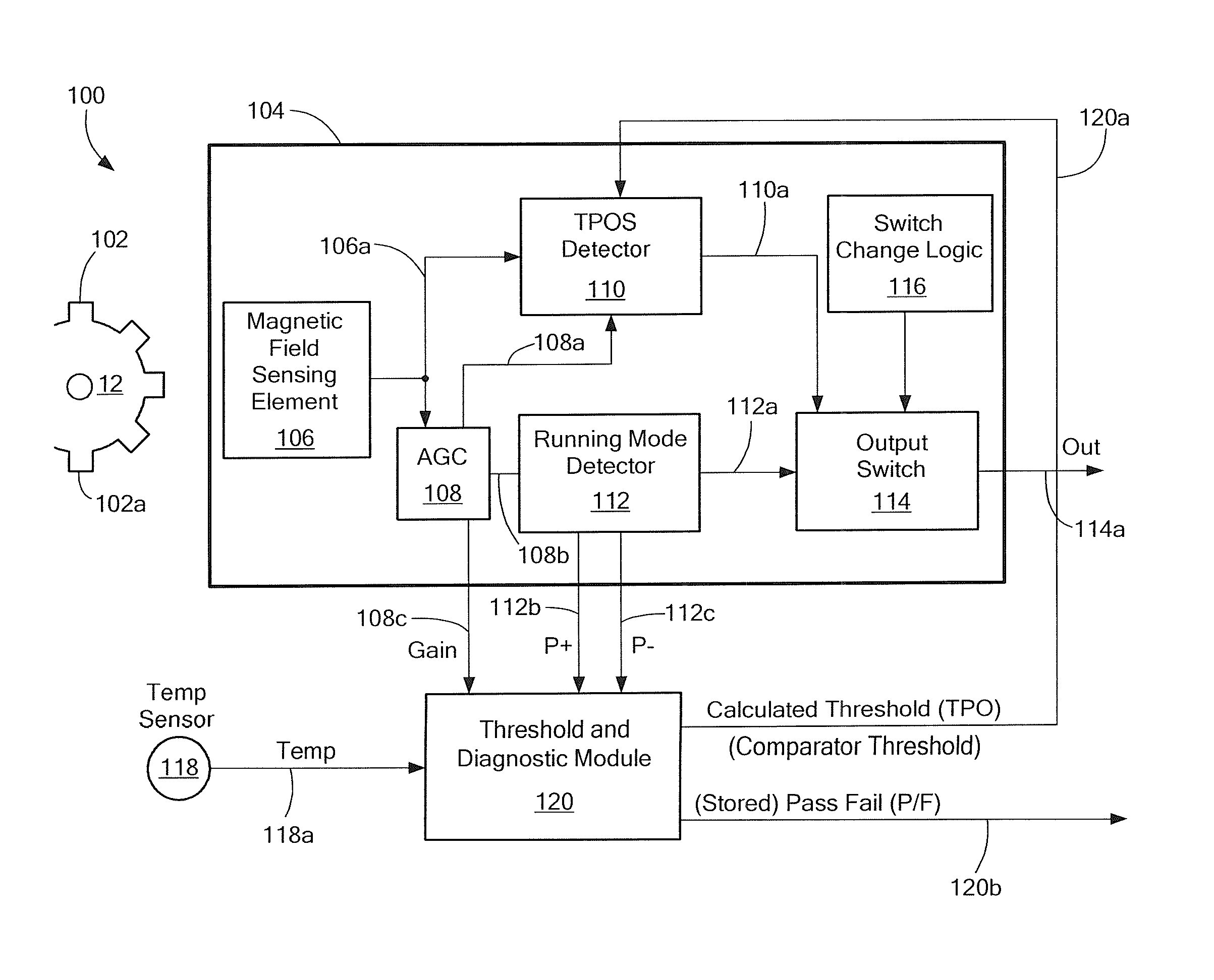
[0034]As used herein, the term “magnetic field sensing element” is used to describe a variety of electronic elements that can sense a magnetic field. The magnetic field sensing elements can be, but are not limited to, Hall effect elements, magnetoresistance elements, or magnetotransistors. As is known, there are different types of Hall effect elements, for example, a planar Hall element, a vertical Hall element, and a circular Hall element. As is also known, there are different types of magnetoresistance elements, for example, a giant magnetoresistance (GMR) element, an anisotropic magnetoresistance element (AMR), a tunneling magnetoresistance (TMR) element, an Indium antimonide (InSb) sensor, and a magnetic tunnel junction (MTJ).

[0035]A so-called “circular vertical Hall” (CVH) sensing element, another type of magnetic field sensing element, which includes a plurality of vertical ...


PUM


Abstract

A magnetic field sensor includes a true power on state (TPOS) detector for which a measured threshold value is stored prior to power down and recalled upon power up. A corresponding method is associated with the magnetic field sensor.

Description

CROSS REFERENCE TO RELATED APPLICATIONS[0001]Not Applicable.STATEMENT REGARDING FEDERALLY SPONSORED RESEARCH[0002]Not Applicable.FIELD OF THE INVENTION[0003]This invention relates generally to magnetic field sensors for sensing a rotation or a movement of an object and, more particularly, to a magnitude field sensor that generates a measured threshold value that can be stored in a memory device and later recalled.BACKGROUND OF THE INVENTION[0004]Various types of magnetic field sensing elements are known, including Hall effect elements and magnetoresistance elements. Magnetic field sensors generally include a magnetic field sensing element and other electronic components. Some magnetic field sensors also include a fixed permanent magnet.[0005]Magnetic field sensors provide an electrical signal representative of a sensed magnetic field, or, in some embodiments, fluctuations of the magnetic field associated with the magnet. In the presence of a moving ferromagnetic object, the magnetic...

Claims


Application Information

Patent Timeline
Patent Type & Authority Patents(United States)
IPC IPC(8): G01B7/30
CPCG01D18/008G01P3/488G01D5/142G01D5/2449G01D5/247G01D5/145
Inventor FOLETTO, ANDREACISAR, PETERSHOEMAKER, ERIC
Owner ALLEGRO MICROSYSTEMS INC
Why Eureka
Try Eureka