MEMS magnetic field sensor

a magnetic field and sensor technology, applied in the direction of flexible microstructure devices, resistance/reactance/impedence, instruments, etc., can solve the problem of unsatisfactory mechanical displacement and achieve the effect of maximizing mechanical displacement, maximizing displacement, and improving sensing capability

Active Publication Date: 2017-10-31
LG INNOTEK CO LTD
View PDF10 Cites 4 Cited by
  • Summary
  • Abstract
  • Description
  • Claims
  • Application Information

AI Technical Summary

Benefits of technology

[0011]As described above, according to the magnetic field sensor of the embodiment, since the magnetic field is detected using two drive electrodes without the fixed electrode, the mechanical displacement can be maximized so that the sensing capability can be improved.
[0012]In addition, when the AC input power is applied to the magnetic field sensor, the displacement can be maximized by matching the AC frequency with the mechanical resonance frequency of the sensor. In addition, the stoppers can be provided to prevent the mechanical displacement from exceeding a critical value, so that device damage can be prevented.
[0013]In addition, the metallic layer having the electrical conductivity is formed at a portion of the magnetic field sensor to increase the mobility of charges so that the reaction reliability and the reaction speed can be increased.

Problems solved by technology

However, since Lorenz force used to sense the magnetic field is significantly weaker than gravity, satisfactory mechanical displacement may not be obtained due to the limitation in the design of a sensor structure such as a spring.
In addition, when an AC current or a DC current is applied to the drive electrode for the driving of the drive electrode to detect a varied signal, a desirable signal may be not detected due to the mixture of currents.

Method used


Image

  • MEMS magnetic field sensor
  • MEMS magnetic field sensor
  • MEMS magnetic field sensor

Examples


first embodiment

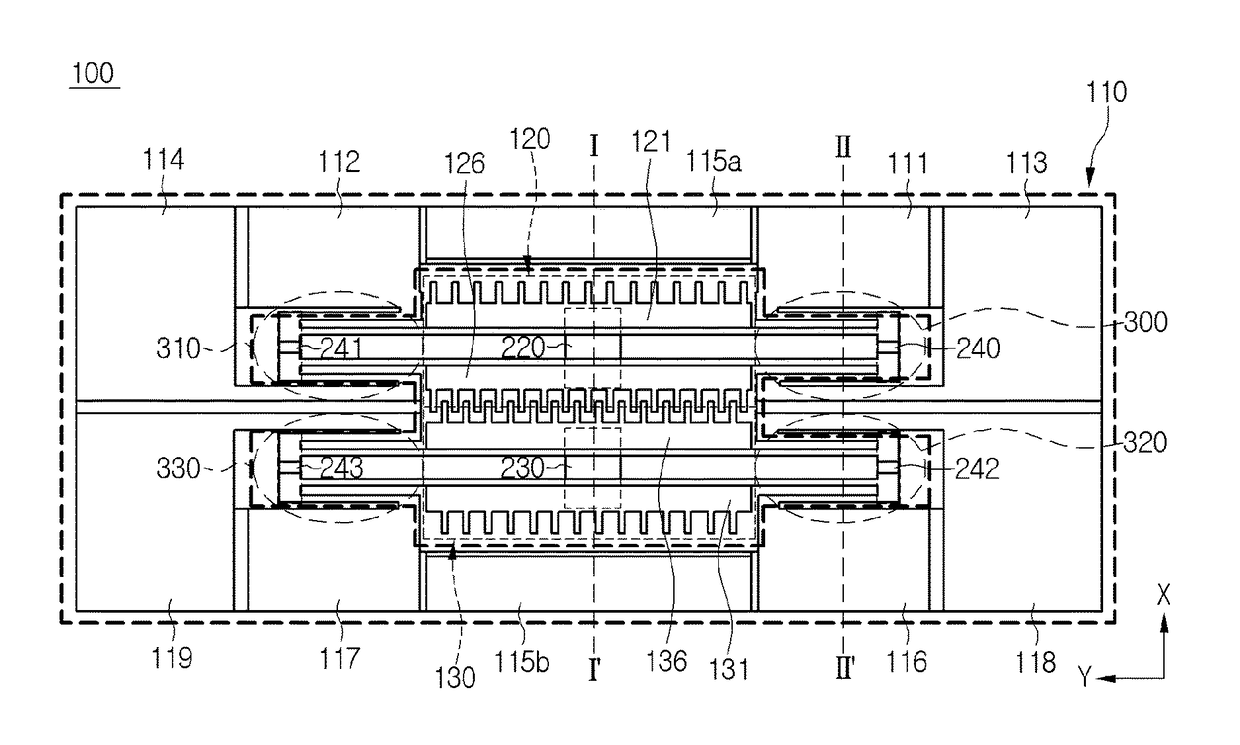
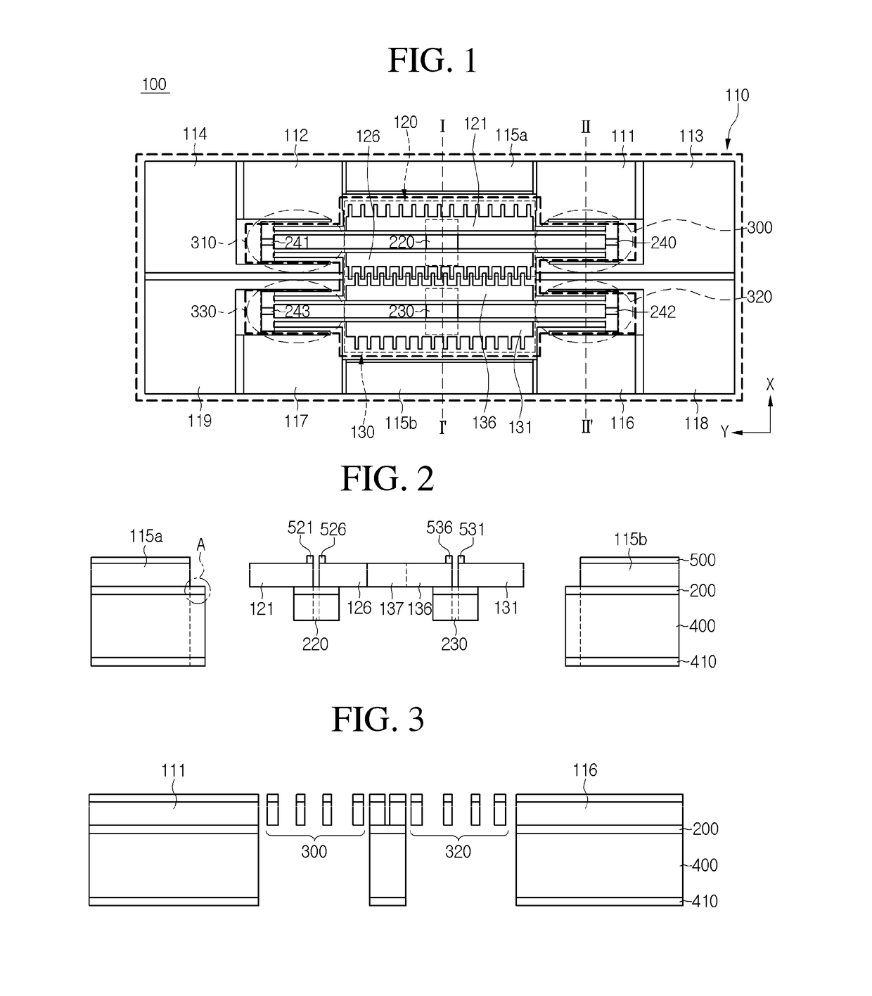
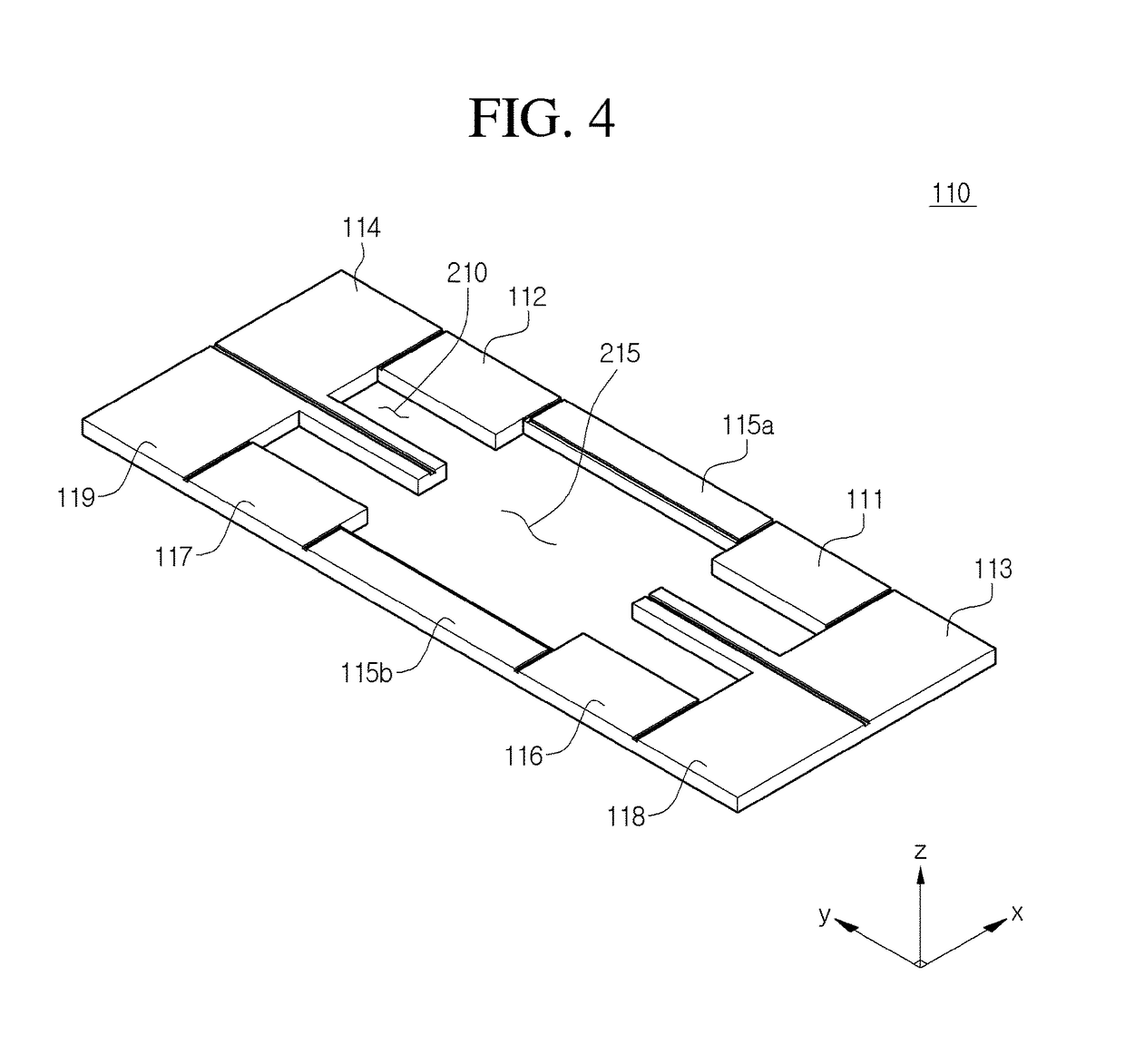
[0034]FIG. 1 is a top view showing a magnetic field sensor and FIG. 2 is a sectional view of the magnetic field sensor taken along line I-I′ of FIG. 1. FIG. 3 is a sectional view showing the magnetic field sensor taken along line II-II′, and FIGS. 4 to 6 are enlarged views showing elements of FIG. 1.

[0035]Referring to FIG. 1, the magnetic field sensor according to the embodiment includes a fixed substrate 110, a drive electrode part 120, and a plurality of elastic parts 300, 310, 320, and 330, which are elements of the MEMS.

[0036]MEMS refers to a technology of producing micro mechanical structures, such as a high-density integrated circuit, a micro gear, and a hard disk, by machining silicon, crystal or glass. Micro machine is produced with the precision of micrometers or less ( 1 / 1,000,000 meters) through the MEMS technology. Semiconductor micro-processing technology of repeatedly performing deposition and etching processes is employed for the structure of the MEMS. Electrostatic ...

second embodiment

[0190]A magnetic field sensor 100A as shown in FIG. 19 includes a fixed substrate 110, drive electrode parts 120 and 130, and a plurality of elastic parts 300, 310, 320, and 330 similarly to the magnetic field sensor of FIG. 1.

[0191]The fixed substrate 110 supports the drive electrode parts 120 and 130 and the elastic parts 300, 310, 320, and 330.

[0192]The drive electrode parts 120 and 130 are provided in a cavity 215 of the fixed substrate 110, and include the first drive electrode 120 surrounded by first and second sensing electrodes 113 and 114 and the first and second power electrodes 111 and 112 to receive power, and a second drive electrode 130 surrounded by the third and four sensing electrodes 118 and 119 and the third and fourth power electrode 116 and 117 to receive power.

[0193]The first drive electrode 120 includes a first reference electrode 121 and a first variable electrode 126 extending in a y axial direction and at least one coupling part 220 to couple the first ref...

third embodiment

[0202]A magnetic field sensor 100B as shown in FIG. 20 includes a fixed substrate 110, drive electrode parts 120 and 130, and a plurality of elastic parts 300, 310, 320, and 330 similarly to the magnetic field sensor of FIG. 1.

[0203]The fixed substrate 110 supports the drive electrode parts 120 and 130 and the elastic parts 300, 310, 320, and 330.

[0204]The drive electrode parts 120 and 130 are provided in a cavity 215 of the fixed substrate 110, and include the first drive electrode 120 surrounded by first and second sensing electrodes 113 and 114 and the first and second power electrodes 111 and 112 to receive power, and a second drive electrode 130 surrounded by the third and four sensing electrodes 118 and 119 and the third and fourth power electrode 116 and 117 to receive power.

[0205]The first drive electrode 120 includes a first reference electrode 121 and a first variable electrode 126 extending in a y axial direction and at least one coupling part 220 to couple the first ref...


PUM


Abstract

The disclosure provides a magnetic field sensor for sensing the magnetic field caused by a current to be measured, which includes: substrate; a first drive electrode with a path for flowing a reference current supplied from the substrate arranged so as to be moveable by the magnetic field of the current to be measured; and a second drive electrode with a path for flowing a reference current supplied from the substrate arranged so as to be moveable by the magnetic field of the current to be measured, thus measuring the variation of a capacitance caused by the movement of the first drive electrode and the second drive electrode. Hence, the sensing is achieved by the two drive electrodes with no reference electrode, thus maximizing the mechanical displacement to improve the sensing capability.

Description

CROSS-REFERENCE TO RELATED PATENT APPLICATIONS[0001]This application is a U.S. National Stage Application under 35 U.S.C. §371 of PCT Application No. PCT / KR2014 / 003585, filed Apr. 24, 2014, which claims priority to Korean Patent Application No. 10-2013-0050332, filed May 3, 2013, whose entire disclosures are hereby incorporated by reference.TECHNICAL FIELD[0002]The embodiment relates to an MEMS magnetic field sensor.BACKGROUND ART[0003]In general, a micro electro mechanical systems (MEMS) magnetic field sensor based on a capacitive sensing technology includes a drive electrode, which is movable n reaction to a magnetic field, and a fixed electrode which senses the variation of capacitance corresponding to the drive electrode.[0004]A capacitive MEMS magnetic field sensor is disclosed in U.S. Pat. No. 6,664,786.[0005]Regarding the principle of the magnetic field sensor, if a reference current is applied to a drive electrode in a predetermined direction, the drive electrode moves in a ...

Claims


Application Information

Patent Timeline
Patent Type & Authority Patents(United States)
IPC IPC(8): G01R33/02G01R33/028
CPCG01R33/0286B81B3/00G01R27/26G01R33/02
Inventor SEO, SANG WONKO, YONG JUNKWON, SEUNG HWASEO, JEONG GIJI, CHIL YOUNGCHOI, WAN SEOP
Owner LG INNOTEK CO LTD
Why Eureka
Try Eureka