
Image pickup apparatus

a technology of image pickup and angular velocity sensor, which is applied in the field of image pickup apparatus, can solve the problems of noise in the acceleration sensor, the difficulty of the angular velocity sensor to accurately detect the shift camera shake, and the adverse effect of the shift camera shake on the captured imag

Active Publication Date: 2014-05-27
FUJIFILM CORP
View PDF7 Cites 10 Cited by
  • Summary
  • Abstract
  • Description
  • Claims
  • Application Information

AI Technical Summary

Benefits of technology

The present invention provides an image pickup apparatus that can correct camera shake accurately while in use and even when using mechanical movable sections. It ensures precise camera shake correction without being influenced by the movements of the camera. Additionally, it enables easy and quick zooming, focusing, or aperture control while maintaining accuracy in camera shake correction.

Problems solved by technology

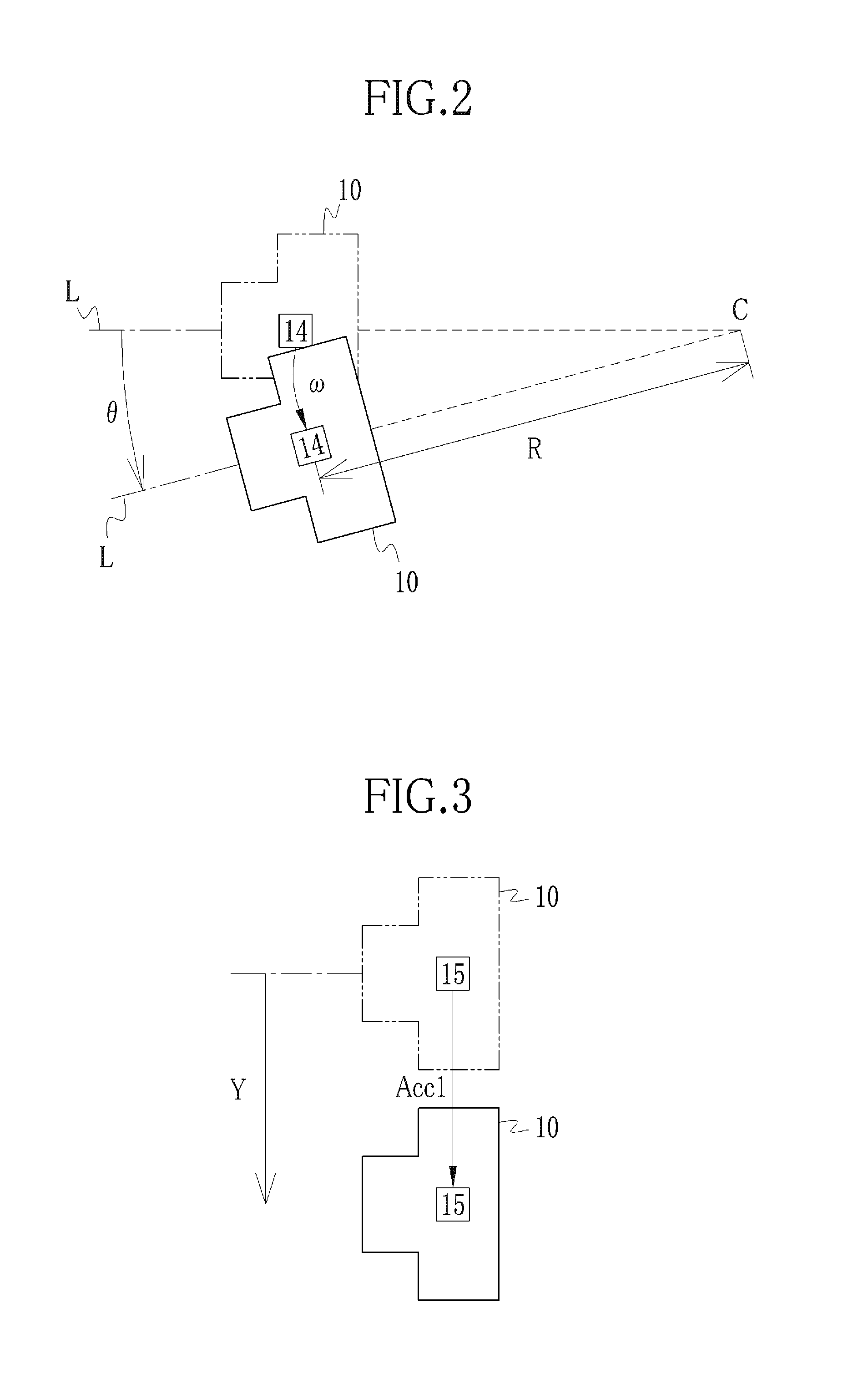
In macro image capturing at high magnification or the like, the shift camera shake affects the captured image adversely more than the angle camera shake.
However, it is difficult for the angular velocity sensor to accurately detect the shift camera shake.
It is because, while the movable sections operate, vibration of the image pickup apparatus in accordance with an internal acceleration thereof due to the movable sections results in noise in the angular velocity sensor and the acceleration sensor.
As the camera shake correction mechanism is suspended while the lens unit operates, the image quality of the through-image or the image looked through the viewfinder degrades due to the camera shake, and thereby it becomes harder to determine the framing of the image to be captured.
In the macro image capturing, in particular, since the magnification is high, degradation of the image quality is prominent even when slight camera shake occurs.
Thus, there is a problem in that the image quality of the moving image degrades since the camera shake correction mechanism is suspended every time the zooming operation or the like is performed.

Method used


Image

  • Image pickup apparatus
  • Image pickup apparatus
  • Image pickup apparatus

Examples


first embodiment

[0037][First Embodiment]

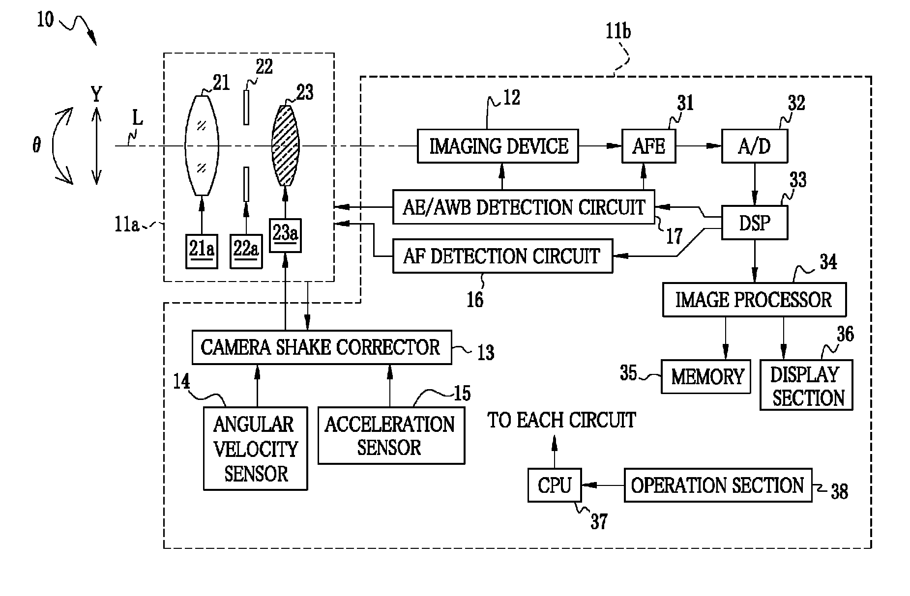
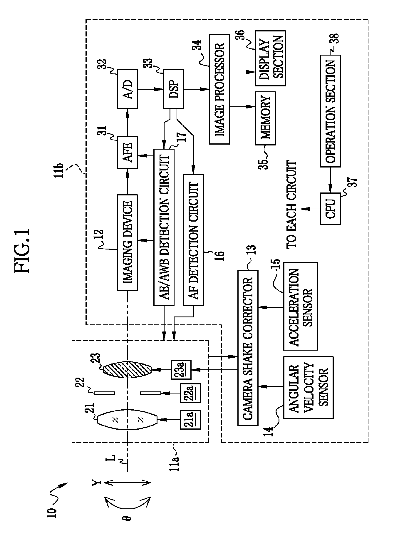
[0038]An image pickup apparatus 10 shown in FIG. 1 is used as a digital camera, a security camera, or the like. The image pickup apparatus 10 includes a lens unit 11a and a camera body 11b. In the case of a compact digital camera, the lens unit 11a is provided to be movable in and out of the camera body 11b. In the case of a digital single-lens reflex camera, the lens unit 11a is detachably attached to the camera body 11b.

[0039]The camera body 11b includes an imaging device 12, a camera shake corrector 13, a angular velocity sensor 14, an acceleration sensor 15, an AF (automatic focus) detection circuit 16, an AE / AWB (automatic exposure / automatic white balance) detection circuit 17, an image processing system mainly consisting of an image processor 34, a CPU 37, and the like.

[0040]The lens unit 11a has an imaging optical system constituted by a lens group 21, an aperture stop 22, and a camera shake correction lens 23. The lens group 21 is depicted as one len...

second embodiment

[0068][Second Embodiment]

[0069]According to the above first embodiment, the translational acceleration calculator 55 accurately obtain the second translational acceleration Acc2 by comparing the frequency component of the internal acceleration with the cut-off frequency fc of the HPF 53 and subtracting the internal acceleration having the frequency component higher than the cut-off frequency fc from the first translational acceleration Acc1. However, the HPF 53 can be omitted. Further, it is usual that the movable sections are driven by a particular driving pattern. In this case, it is possible to obtain the internal acceleration based on the driving pattern.

[0070]FIG. 6 illustrates a camera shake correction mechanism which is not provided with the HPF 53 but which is provided with an internal acceleration calculator 73. A detection signal from the acceleration sensor 15, from which noise is removed by the LPF 51, is converted into a digital signal by the A / D converter 52, and then ...


PUM


Abstract

At the time of occurrence of camera shake, an angular velocity sensor detects an angular velocity. A rotation angle calculator integrates the angular velocity to calculate angle camera shake. A translational acceleration calculator subtracts an internal acceleration caused during operation of a lens unit from a first translational acceleration detected by an acceleration sensor, so as to calculate a second translational acceleration. A translational velocity calculator integrates the second translational acceleration to calculate a translational velocity. A rotation radius calculator calculates a rotation radius based on the angular velocity and the translational velocity. A shake amount calculator calculates a camera shake amount based on the angle camera shake and the rotation radius. An actuator drives a camera shake correction lens in a direction for canceling the camera shake amount.

Description

[0001]This application is a Continuation of PCT / JP2012 / 059863 filed on Apr. 11, 2012, which claims priority under 35 U.S.C. 119(a) to Patent Application No. 2011-088135 filed in Japan, all which are hereby expressly incorporated by reference into the present application.BACKGROUND OF THE INVENTION[0002]1. Field of the Invention[0003]The present invention relates to an image pickup apparatus having a camera shake correction function.[0004]2. Description of the Related Art[0005]As an image pickup apparatus, as well known, there are a digital camera, a monitoring camera, and the like. The image pickup apparatus is generally provided with an automatic focusing mechanism and an automatic exposure control mechanism. Recently, the image pickup apparatus is further provided with a camera shake correction mechanism so as to suppress image quality degradation of a captured image occurring due to camera shake. The camera shake occurs when the image pickup apparatus rotates or shifts in accorda...

Claims


Application Information

Patent Timeline
Patent Type & Authority Patents(United States)
IPC IPC(8): H04N5/232H04N5/228H04N23/40
CPCG03B5/00H04N5/23258G03B2205/0007H04N5/2328H04N5/23287G03B2217/005H04N23/6812H04N23/687H04N23/685
Inventor IMANISHI, KAZUTAKA
Owner FUJIFILM CORP
Learn More