Method for manufacturing three-dimensional shaped object and three-dimensional shaped object obtained by the same

a three-dimensional shaped object and three-dimensional shaped object technology, applied in the direction of foundry moulding apparatus, instruments, foundry patterns, etc., can solve the problems of unsatisfactory upward warp of the three-dimensional shaped object and the peeling thereof from the base plate, and the inability to achieve the shape accuracy of the resulting three-dimensional shaped object, etc., to achieve shorten the manufacturing time, reduce the proportion, and high energy

Inactive Publication Date: 2014-05-27
PANASONIC CORP
View PDF27 Cites 9 Cited by
  • Summary
  • Abstract
  • Description
  • Claims
  • Application Information

AI Technical Summary

Benefits of technology

[0021]In accordance with the present invention, the high-density portion is formed only at required position, and thereby making it possible to shorten the manufacturing time and also to reduce the proportion of the high-density portion which essentially requires a high energy for the formation thereof. This leads to an achievement of the reduction of the manufacturing cost of the shaped object.
[0022]According to the manufacturing method of the present invention, there is provided a reduced proportion of the high-density portion in the entire three-dimensional shaped object, since the high-density portion is formed only at required position. Therefore, in light of the fact that the high-density portion is considered “portion where a shrinkage ratio is comparatively large due to a cooling and subsequent solidification of the molten powder”, the present invention can produce the three-dimensional shaped object with a percentage of the large shrinkage portion being kept as low as possible. This can contribute to a prevention or reduction of an upward warping of the three-dimensional shaped object, thus making it possible to prevent the three-dimensional shaped object (i.e., solidified layer) from peeling from the surface of the base plate. In other words, not only it becomes possible to newly provide a powder layer with a predetermined thickness on the solidified layer, but also a shape accuracy of the obtained three-dimensional shaped object is improved.
[0023]Furthermore, it was inevitably required in the prior art to design on preliminary assumption of phenomena such as “upward warping” and “peeling” in order to achieve the shape accuracy of the three-dimensional shaped object. However, it is possible according to the present invention to prevent “upward warping” and “peeling” while reducing the manufacturing time and manufacturing cost only by providing the high-density portion at a required position of the shaped object. In other words, the present invention is also very useful in that it is possible to suitably design the shaped object while preventing an increase in the manufacturing time and manufacturing cost in spite of those unpredictable phenomena.

Problems solved by technology

However, a shrinkage phenomenon can occur upon the solidification.
The upward warp of the three-dimensional shaped object and the peeling thereof from the base plate are not desirable since it becomes difficult to manufacture a desired three-dimensional shaped object.
For example, when the three-dimensional shaped object (i.e., solidified layer) warps upward, it becomes impossible to achieve a shape accuracy of the resulting three-dimensional shaped object.
Also, when it becomes impossible to newly provide a powder layer with a predetermined thickness on the solidified layer due to the upward warping of the solidified layer (e.g., when the solidified layer warps upward to the extent more than the thickness of a powder layer to be newly provided), it will become impossible to uniformly provide the new powder layer by the squeegee process.
Since the outer shell portion has a solidified density higher than that of the inner core portion, a formation of the outer shell portion requires a high energy and also takes a longer time.
Therefore, in the invention of JP-T-8-504139, the entire periphery of the three-dimensional shaped object is coated with a material with a generally uniform thickness (see FIG. 17) and it is by no means satisfactory from the viewpoint of the manufacturing cost and time.

Method used


Image

  • Method for manufacturing three-dimensional shaped object and three-dimensional shaped object obtained by the same
  • Method for manufacturing three-dimensional shaped object and three-dimensional shaped object obtained by the same
  • Method for manufacturing three-dimensional shaped object and three-dimensional shaped object obtained by the same

Examples


Embodiment Construction

[0076]The present invention will be hereinafter described in more detail with reference to the accompanying drawings.

[Selective Laser Sintering Method]

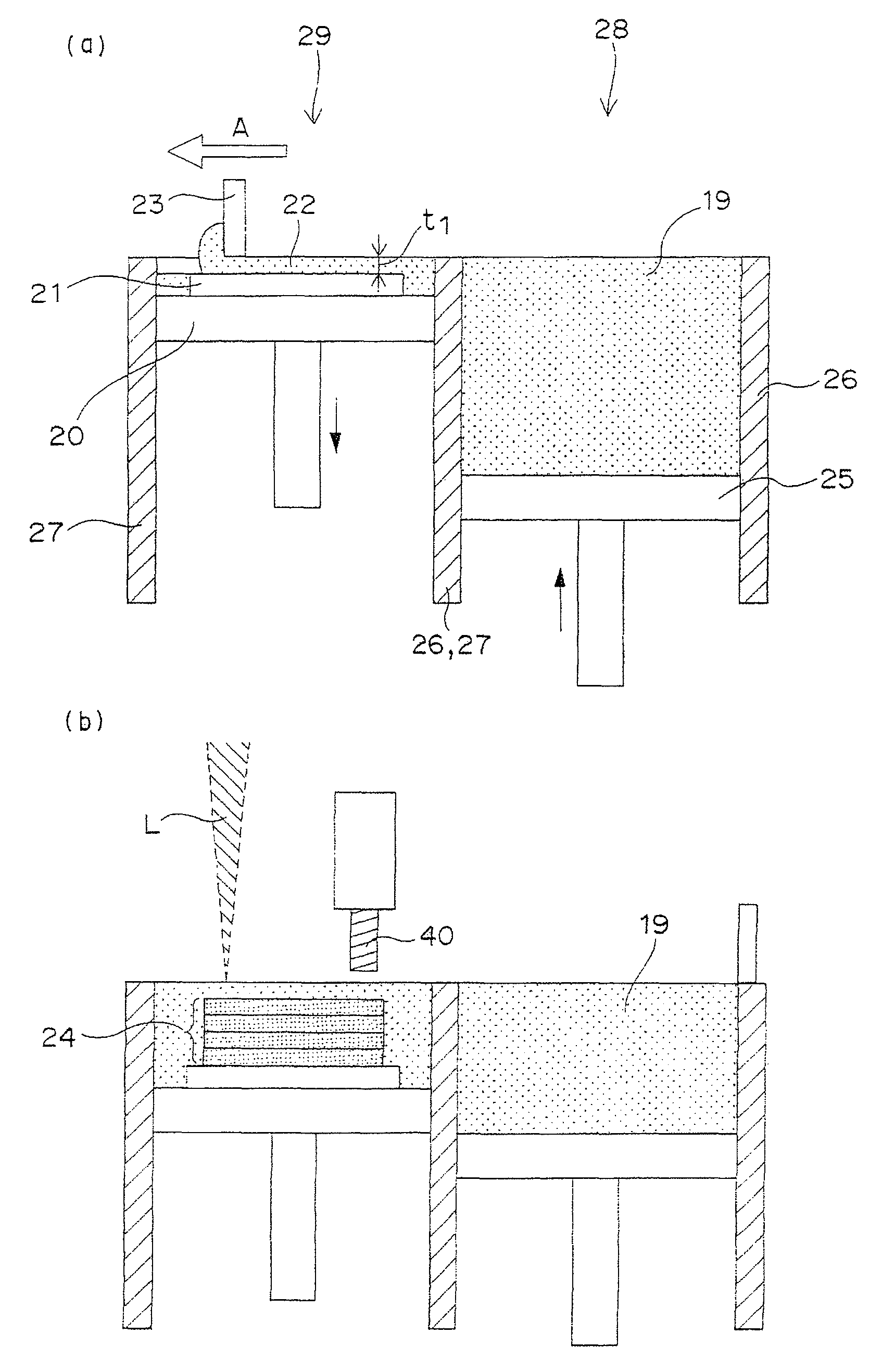
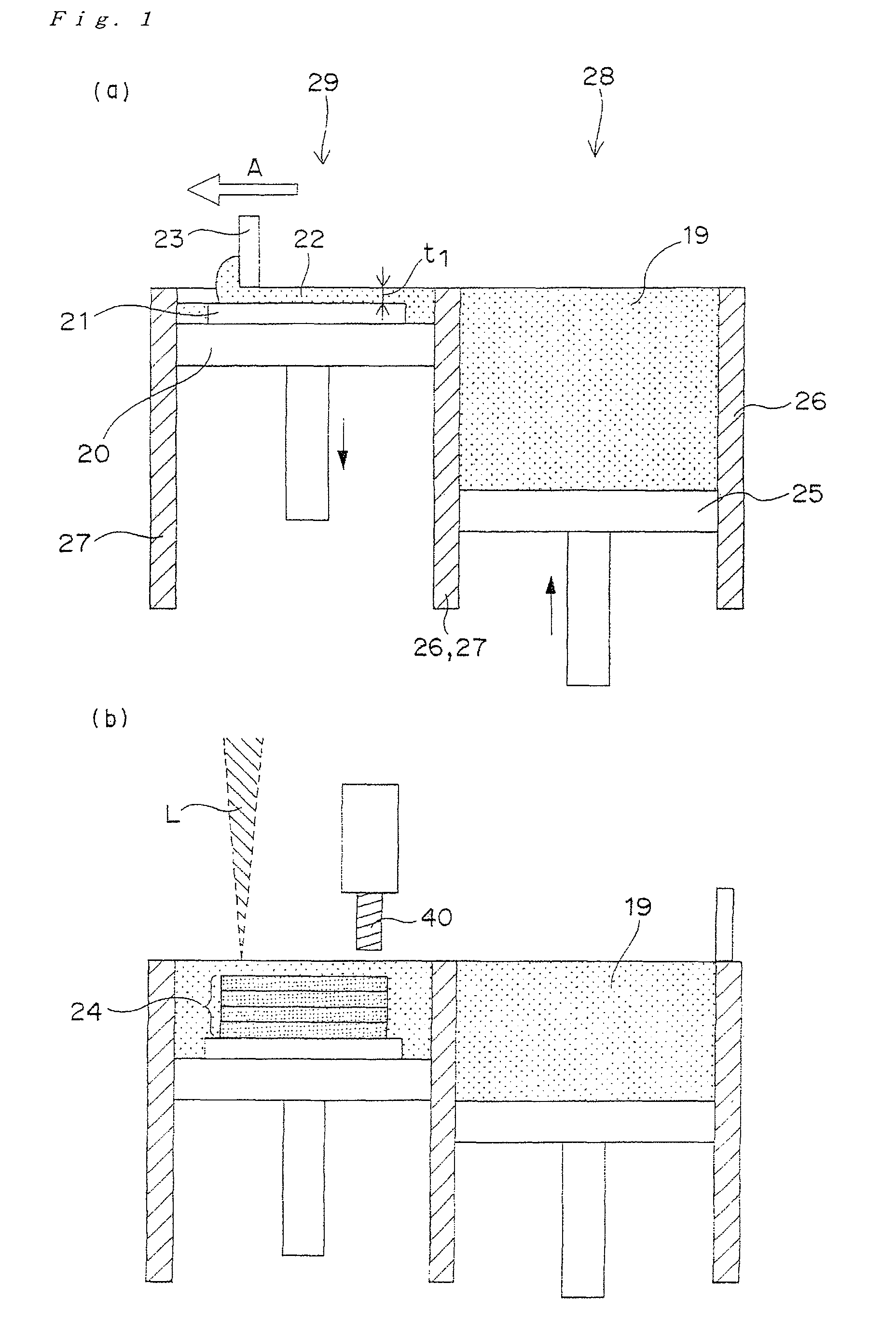
[0077]First, a selective laser sintering method, on which the manufacturing method of the present invention is premised, will be described. FIG. 1, FIG. 3 and FIG. 4 show functions and constitutions, which enable execution of the selective laser sintering method, of a laser-sintering / milling hybrid machine 1. The laser-sintering / milling hybrid machine 1 is mainly provided with a “powder layer forming means 2 for forming a powder layer by providing a powder such as a metal powder or a resin powder in a predetermined thickness”; a “forming table 20 which is capable of vertically elevating / descending by cylinder drive in a forming tank 29 whose outer periphery is surrounded with a wall 27”; a “base plate for shaped object 21 which is disposed on the forming table 20 and serves as a platform of a shaped object”; a “laser-beam irradiation ...


PUM

PropertyMeasurementUnit
mean particle diameteraaaaaaaaaa
lengthaaaaaaaaaa

Abstract

There is provided a method for manufacturing a three-dimensional shaped object. The method of the present invention comprises the repeated steps of: (i) forming a solidified layer by irradiating a predetermined portion of a powder layer on a base plate with a light beam, thereby allowing a sintering of the powder in the predetermined portion or a melting and subsequent solidification thereof; and (ii) forming another solidified layer by newly forming a powder layer on the resulting solidified layer, followed by the irradiation of a predetermined portion of the powder layer with the light beam; wherein the solidified layers are formed such that they have a high-density portion whose solidified density is 95 to 100% and a low-density portion whose solidified density is 0 to 95% (excluding 95%); and wherein the high-density portion is a portion of the three-dimensional shaped object, to which the force is applied when the three-dimensional shaped object is used.

Description

TECHNICAL FIELD[0001]The present invention relates to a method for manufacturing a three-dimensional shaped object, and also relates to the three-dimensional shaped object. More particularly, the present invention relates to a method for manufacturing a three-dimensional shaped object with a plurality of solidified layers stacked integrally by repeating the step of forming a solidified layer by irradiating a predetermined portion of a powder layer with a light beam, and also relates to the three-dimensional shaped object obtained by such manufacturing method.BACKGROUND OF THE INVENTION[0002]Heretofore, a method for manufacturing a three-dimensional shaped object by irradiating a powder with a light beam has been known (such method can be generally referred to as a “selective laser sintering method”). Such method can produce a three-dimensional shaped object with a plurality of solidified layers stacked integrally by repeating the step (i) of forming a solidified layer by irradiating...

Claims


Application Information

Patent Timeline
Patent Type & Authority Patents(United States)
IPC IPC(8): G06F19/00
CPCB29C2793/009B22F5/007B22C9/061B22C9/065B22F2207/17B33Y10/00B33Y80/00B33Y30/00Y02P10/25B22F10/28B22F12/44B22F12/49B22F10/66B22F12/33B22F10/36B22F10/38B22F12/41B22F3/16B22F3/105B29C67/00
Inventor ABE, SATOSHITAKENAMI, MASATAKAFUWA, ISAOHIGASHI, YOSHIKAZUYOSHIDA, NORIO
Owner PANASONIC CORP
Why Eureka
Try Eureka