
Lifting system for a transportation system structure

a transportation system and lifting system technology, applied in the direction of lifting devices, inclined ship lifting, hoisting equipment, etc., can solve the problems of high mechanical demands on the lifting system, shortening the manipulation time, and bulky structure of the transportation system

Inactive Publication Date: 2014-06-03
INVENTIO AG
View PDF16 Cites 3 Cited by
  • Summary
  • Abstract
  • Description
  • Claims
  • Application Information

AI Technical Summary

Benefits of technology

The invention is a lifting system that has a downwardly-directed foot or positioning piece that is received by a cradle. The cradle has a supporting surface that is complimentary to the foot surface and can adjust the position of the transportation system. The two supporting surfaces are arranged mirror-symmetrically and are horizontally displaceable relative to a vertical central plane to prevent lateral displacement when adjusting the height of a vertical foot axis. The lifting system can have a screw arrangement or a spring arrangement to facilitate actuation of the lifting system.

Problems solved by technology

Firstly, the lifting system must ensure the most perfect possible horizontalization or height adjustment in the range of a few millimeters or centimeters.
Secondly, the transportation system structures are so bulky and heavy that high mechanical demands must be made on the lifting system.
Thirdly, the lifting systems should be rapidly loadable and quick and easy to operate. The at-factory manufacturing assembly of transportation systems can be greatly rationalized if it takes place in an assembly line. Such an assembly line comprises several assembly stations that are passed through in succession by the transportation system structures and loaded at the same time. In each assembly station, during an assembly phase, station-specific assembly steps are executed. On completion of the as-synchronously-as-possible executed assembly phase, during a transport phase the transportation system structures are taken to the respective following assembly stations, and under optimal fabrication conditions the transport of all transportation system structures should also take place as synchronously as possible. It is self-evident that rapid loading and operation of the lifting systems greatly shortens the manipulation times.
Fourthly, the lifting systems should be inexpensive, since a plurality of them, namely several lifting systems for each assembly station, is required.

Method used


Image

  • Lifting system for a transportation system structure
  • Lifting system for a transportation system structure
  • Lifting system for a transportation system structure

Examples


Embodiment Construction

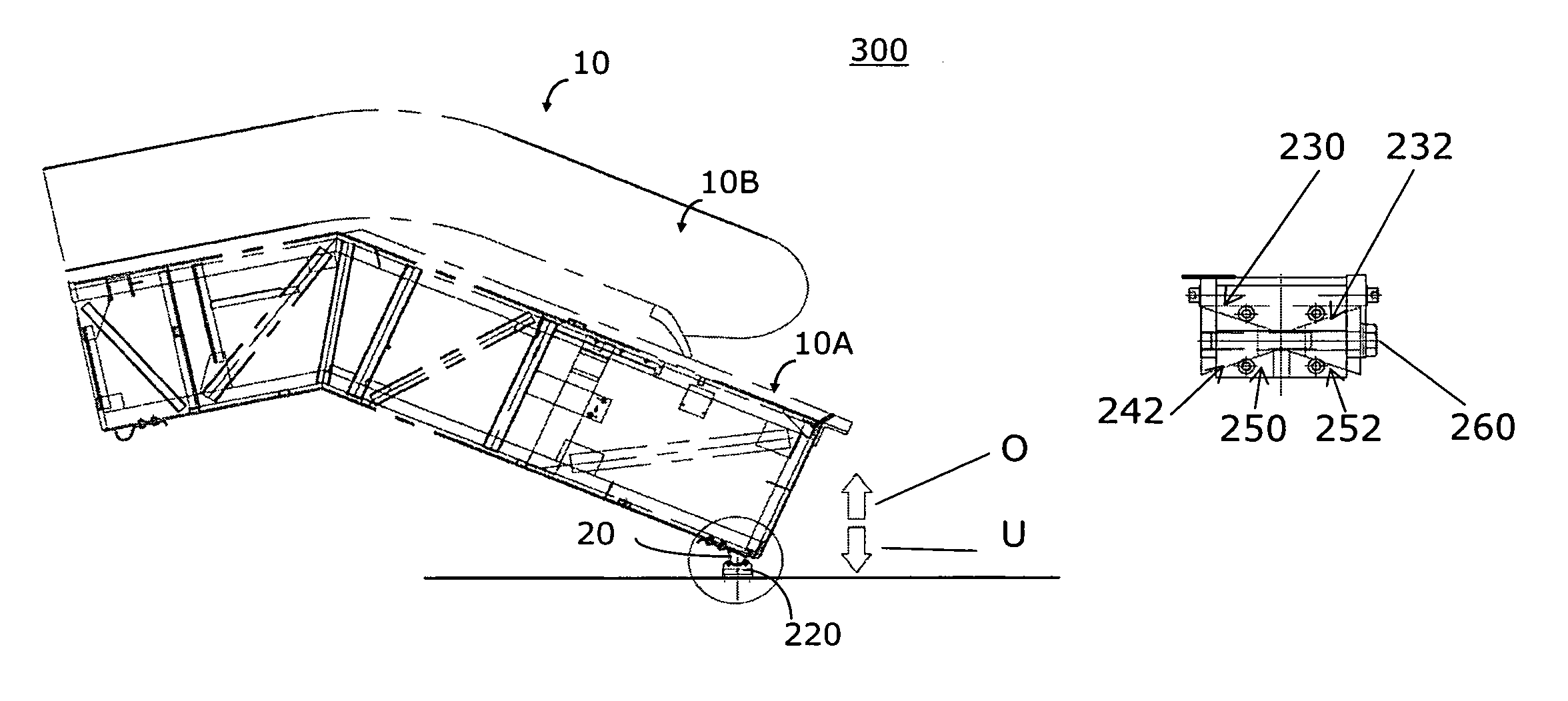
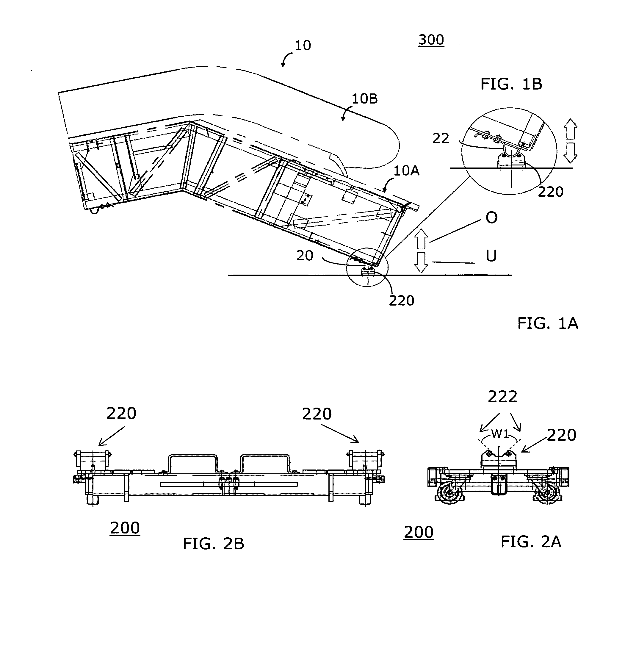
[0039]FIGS. 1A and 1B show a transportation system structure 10, namely a truss 10A of a still unfinished escalator with a balustrade 10B. The transportation system structure 10 has a downward pointing foot or transport foot 20 that that is cradled in a foot cradle 220. The foot 20 and the foot cradle 220 essentially form a lifting system 20 / 220 according to the invention. The foot 20, and along with it the adjoining area of the transportation system structure 10, can be moved upwards and downwards relative to the foot cradle 220 in the direction of the arrows O and U.

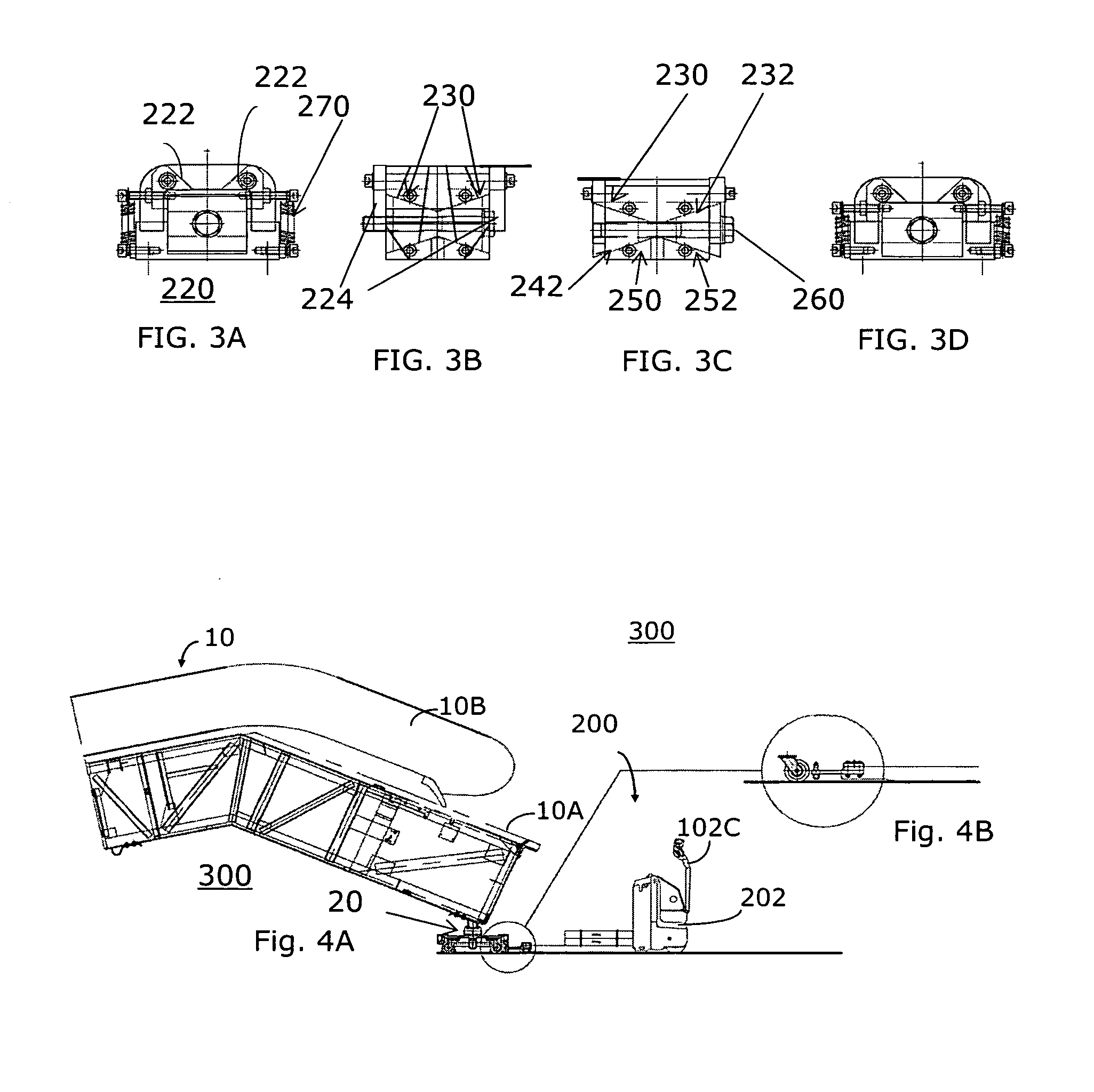
[0040]While the lifting system 20 / 220 that is shown in FIGS. 1A and 1B is stationary and can be, for example, at a generally shown assembly station 410 of an assembly plant 400, FIGS. 2A and 2B show two essentially identical lifting systems 20 / 220 which as a pair in FIG. 2B (left and right) are arranged on a mobile cradle unit of a transportation system cradle unit or of a transportation system cradle 200.

[0041]The foo...


PUM


Abstract

A lifting system for vertical adjustment of a transportation system structure consists of a foot that is fastened onto the transportation system structure and a foot cradle. The foot is bounded on opposite sides by two foot surfaces that are arranged at a foot-surface angle to each other. The foot cradle has two complimentary supporting surfaces against which the foot surfaces rest. The supporting surfaces are vertically movable, allowing the foot and transportation system structure to be raised or lowered, and the vertical adjustment thereby takes place.

Description

[0001]The invention relates to a hoisting system for vertical adjustment of a transportation system structure, a transportation system cradle with a lifting system, an intermediate product for manufacturing assembly of a transportation system structure, and an installation location and an installation method for manufacturing assembly of transportation system structures of the intermediate products. “Manufacturing assembly” is defined as the assembly of various individual parts and subassemblies of an escalator or of a moving walk.BACKGROUND OF THE INVENTION[0002]Lifting systems, within the meaning of the present invention, are used to align transportation system structures in assembly stations with respect to height. The term “transportation system structure” is to be understood as a transportation system, in other words an escalator or moving walk, in an unfinished state during its at-factory manufacturing assembly or a complete assembly, which can be for example, a frame or truss...

Claims


Application Information

Patent Timeline
Patent Type & Authority Patents(United States)
IPC IPC(8): B66F19/00
CPCB66F3/08B66B31/00B66B23/00
Inventor KLEIN, WOLFGANGHEIN, ANDREASMATHEISL, MICHAEL
Owner INVENTIO AG
Learn More