Mobile barrier

a technology of mobile barriers and barriers, applied in the direction of shields, ways, traffic signals, etc., can solve the problems of exposing workers to significant accident risk, requiring significant transportation time and effort, and providing only limited protection to road construction workers, so as to reduce the ability of passing traffic, improve protection, and mitigate the effect of rubber-necking and secondary incidents

Active Publication Date: 2014-06-03
CONCATEN
View PDF77 Cites 24 Cited by
  • Summary
  • Abstract
  • Description
  • Claims
  • Application Information

AI Technical Summary

Benefits of technology

[0009](c1) the trailer supports a ballast member, the ballast member being positioned near a first side of the trailer and the ballast member near a second, opposing side of the trailer, the ballast member offsetting, at least partially, a weight of the plurality of wall sections, and
[0056]The trailer can provide an increased level of physical protection both day and night and workers with a self-contained and enhanced work environment that provides them with basic amenities such as restrooms, water, power, lighting, ventilation and even some possible heating / cooling and shelter. The trailer can also be designed to keep passing motorists from seeing what is going on within the work area and hopefully facilitate better attention to what is going on in front of them. Hopefully, this will reduce both direct and secondary incidents along such construction and maintenance sites.

Problems solved by technology

For example, cones, barrels and flashing lights have been widely used to warn drivers of construction zones, but provide only limited protection to road construction workers in the event a driver fails to take heed.
In addition, conventional barriers require significant time and effort to transport to the work site, and expose workers to significant risk of accident while deploying the barrier at the work site.
Lighter weight materials having high strength are typically disfavored as their reduced weight is less able to withstand, without significant displacement, the force of a vehicular collision.

Method used


Image

  • Mobile barrier
  • Mobile barrier
  • Mobile barrier

Examples


Embodiment Construction

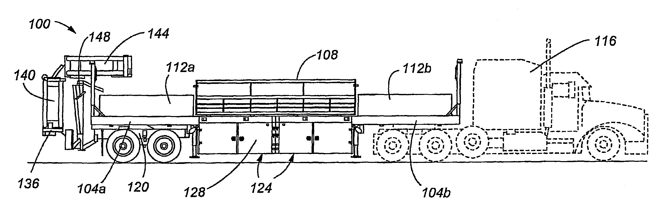
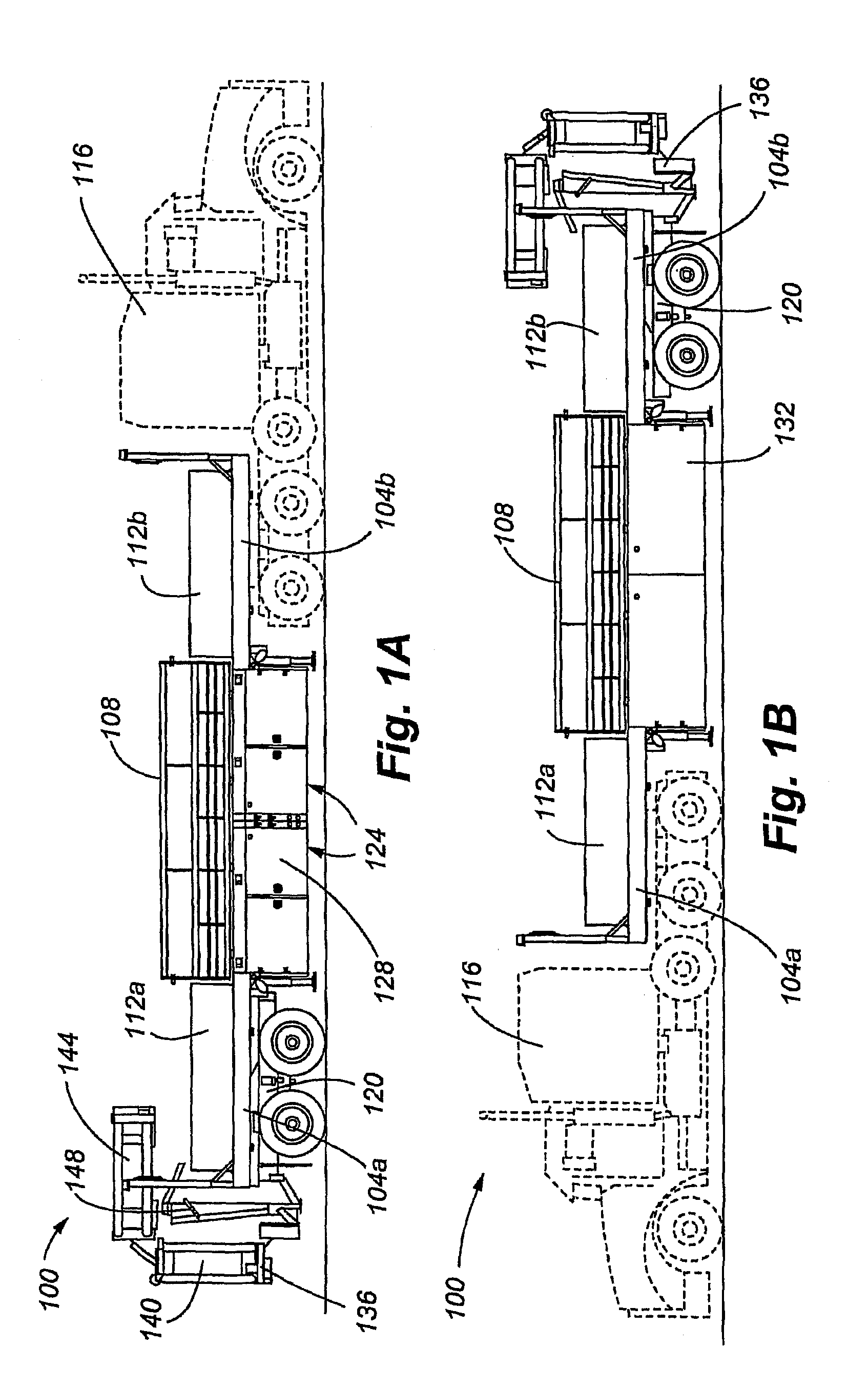
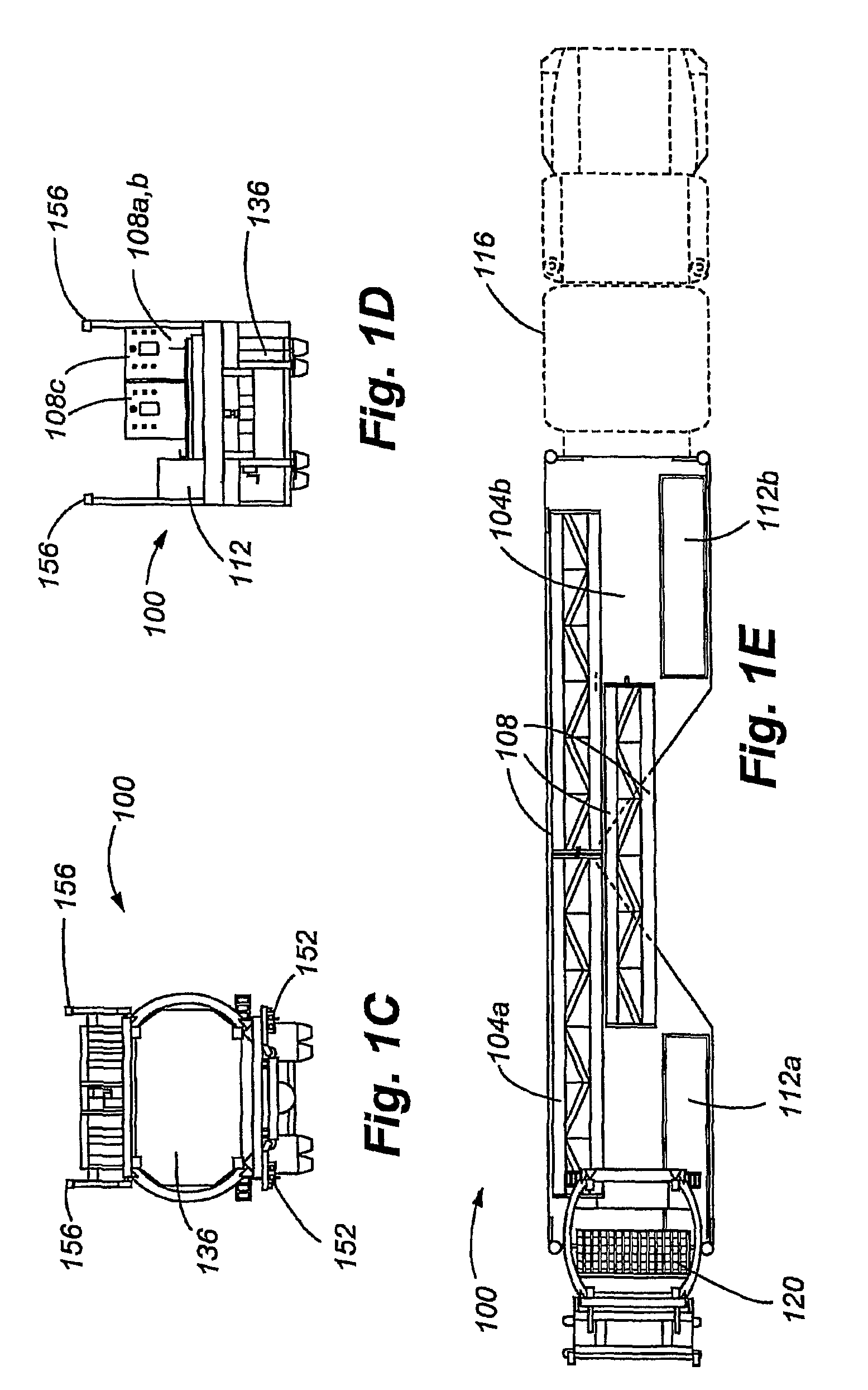
[0091]Embodiments of the present invention are directed to a mobile traffic barrier. In one embodiment, the mobile traffic barrier includes a number of inter-connectable wall sections that can be loaded onto a truck bed. The truck bed itself includes two (first and second) platforms. Each platform includes a king pin (not shown); the king pin providing a connection between the selected platform and either a caboose or a tractor. By enabling the tractor to hook at either end, the trailer can incorporate a rigid fixed wall that is open to the right or left side of the road, depending on the end to which the tractor is connected. The side wall and the ends of the trailer define a protected work area for road maintenance and other operations. The tractor and caboose may exchange trailer ends to change the side to which the wall faces. The dual-hookup, fixed-wall design can enable and incorporate compartments (in the platforms) for equipment and storage, onboard power for lighting, venti...


PUM


Abstract

In one embodiment, a safety trailer has semi-tractor hitches at both ends and a safety wall that is fixed to one side of the trailer. That side, however, can be changed to the right or left side of the road, depending on the end to which the truck attaches. A caboose can be attached at the end of the trailer opposite the tractor to provide additional lighting and impact protection. Optionally, the trailer can be equipped with overhead protection, lighting, ventilation, onboard hydraulics, compressors, generators and other equipment, as well as related fuel, water, storage and restroom facilities and other amenities.

Description

CROSS REFERENCE TO RELATED APPLICATION[0001]The present application claims the benefits of U.S. Provisional Application Ser. Nos. 61 / 267,335, filed Dec. 7, 2009, and 61 / 368,952, filed Jul. 29, 2010, each of which is entitled “MOBILE BARRIER” and are incorporated herein by this reference in their entirety.FIELD OF THE INVENTION[0002]The present invention relates generally to the field of trailers and other types of barriers used to shield road construction workers from traffic. More specifically, the present invention discloses a safety and construction trailer having a fixed safety wall and semi tractor hookups at both ends.BACKGROUND[0003]Various types of barriers have long been used to protect road construction workers from passing vehicles. For example, cones, barrels and flashing lights have been widely used to warn drivers of construction zones, but provide only limited protection to road construction workers in the event a driver fails to take heed. Some construction projects ...

Claims


Application Information

Patent Timeline
Patent Type & Authority Patents(United States)
IPC IPC(8): E01F13/00
CPCB60P3/00F41H11/12F41H11/13E01F15/00F41H5/18E01F13/022F41H13/00F41H11/00F41H5/20F41H5/24
Inventor GROENEWEG, KEVIN, K.
Owner CONCATEN
Why Eureka
Try Eureka