Gas spring mounting assembly and method for metal forming dies

a technology mounting assemblies, which is applied in the direction of forging/hammering/pressing machines, shaping tools, forging presses, etc., can solve the problems of increasing the overall cost and complexity of metal forming dies, requiring substantial lead time, and complicated and expensive problems, and achieves simple machining, easy installation and removal, and greater holding strength

Active Publication Date: 2014-06-10
STANDARD LIFTERS INC
View PDF11 Cites 1 Cited by
  • Summary
  • Abstract
  • Description
  • Claims
  • Application Information

AI Technical Summary

Benefits of technology

[0013]Yet another aspect of the present invention is a gas spring mounting assembly and method for metal forming dies, which securely retains gas springs and other similar die components during both the assembly and maintenance of the metal forming die, and also prevents the gas springs from falling into the die during the production of die formed metal parts. The gas spring mounting assembly and method require only simple machining of the die members and / or components, and uses circumferential clamping about the body portion of the gas spring which makes abutting contact at multiple locations about the outside surface of the gas spring body to provide greater holding strength, while simultaneously centering the gas spring in the center of the blind hole pocket in the die member. The gas spring mounting assembly and method are compatible with a wide variety of differently shaped and sized gas springs, and can be installed anywhere along the length of the gas spring, without requiring special grooves or other retention features on the gas spring body for attachment. The gas spring mounting assembly and method permits the gas spring to be easily installed and removed from an associated die member or component, and provides a good visual indication of the clamp status. The gas spring mounting assembly and method provides a pre-made, modular retainer with an uncomplicated construction that avoids the need for expensive, custom in-house fabrication, which reduces machining cost, is easy to assemble, yet securely retains the gas spring in place with a minimal foot print and profile to facilitate installation in a wide variety of locations in the metal forming die. The gas spring mounting assembly preferably includes a standardized clamping ring design that can be used with either standard flat head cap screws, or with a tapered plug and standard socket head cap screw, so as to provide reduced cost and tool room inventory. The tapered plug embodiment of the gas spring mounting assembly bottoms on the mounting surface, thereby providing consistent clamping pressure, as well as positive protection from overtightening of the clamping ring. The uniquely shaped one-piece split clamping ring is adapted to be economically manufactured by cutting the same from solid plates of metal or the like, preferably arranged in a nested layout, such that the parts can be simply deburrred and surface treated, and do not require any additional machine processes, so as to reduce manufacturing time and cost. Laser and / or abrasive water jet cutting techniques may be used to economically manufacture the split clamping rings, and produce consistently shaped parts. The gas spring mounting assembly and method is efficient in use, economical to manufacture, capable of a long operating life and particularly well adapted for the proposed use.

Problems solved by technology

Current die making processes require carefully machined, precision holes, and recesses in the die set for mounting the individual components, such that the same are quite labor intensive, and require substantial lead time to make, test and set up in a stamping press.
Heretofore, spring devices have been mounted in the various die components and / or die shoes using custom fitting techniques that require time consuming, accurate machining, which increases the overall cost and complexity of the metal forming die.
While such prior art constructions are generally effective, they are complicated and expensive.

Method used


Image

  • Gas spring mounting assembly and method for metal forming dies
  • Gas spring mounting assembly and method for metal forming dies
  • Gas spring mounting assembly and method for metal forming dies

Examples


Embodiment Construction

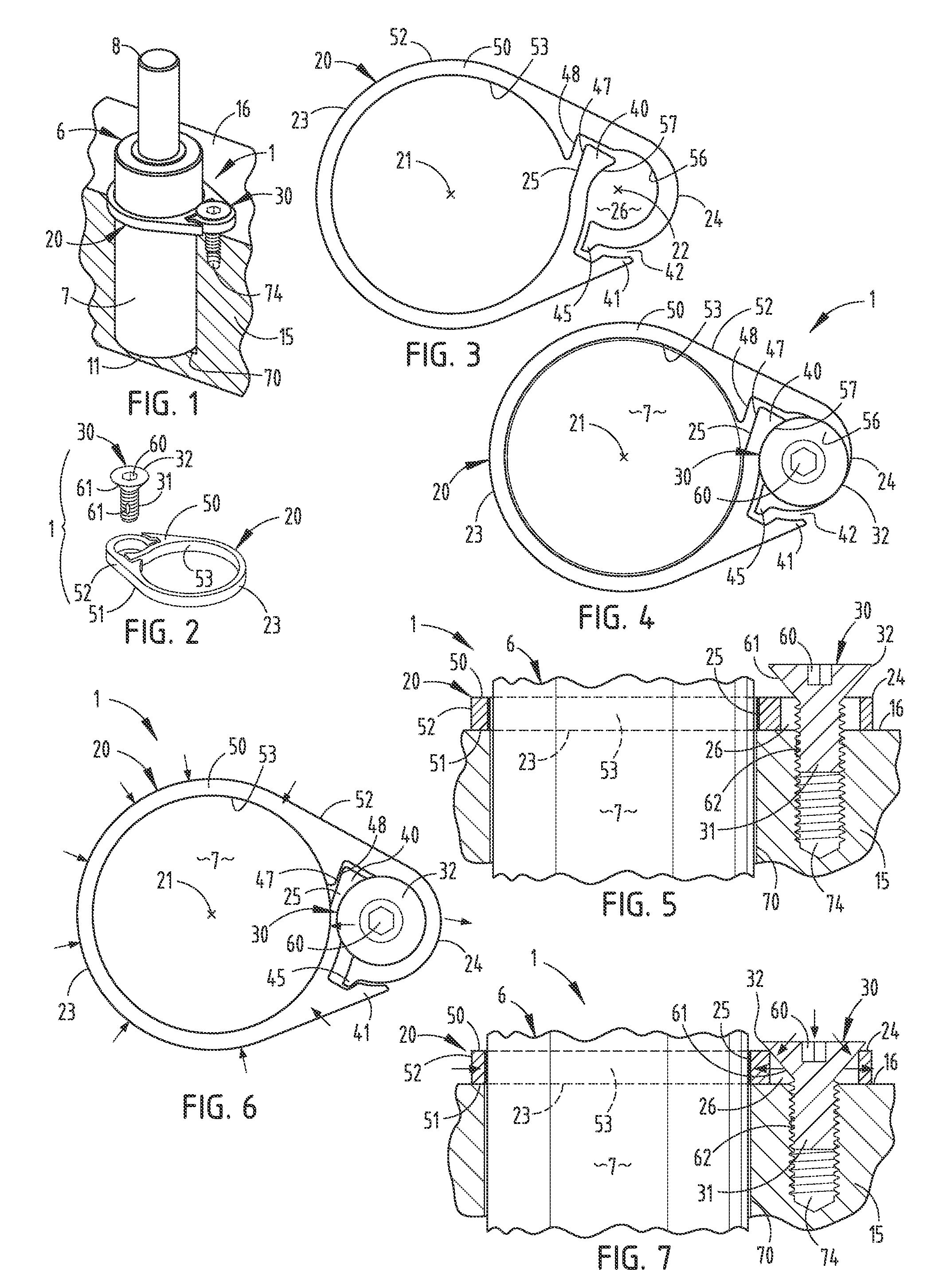
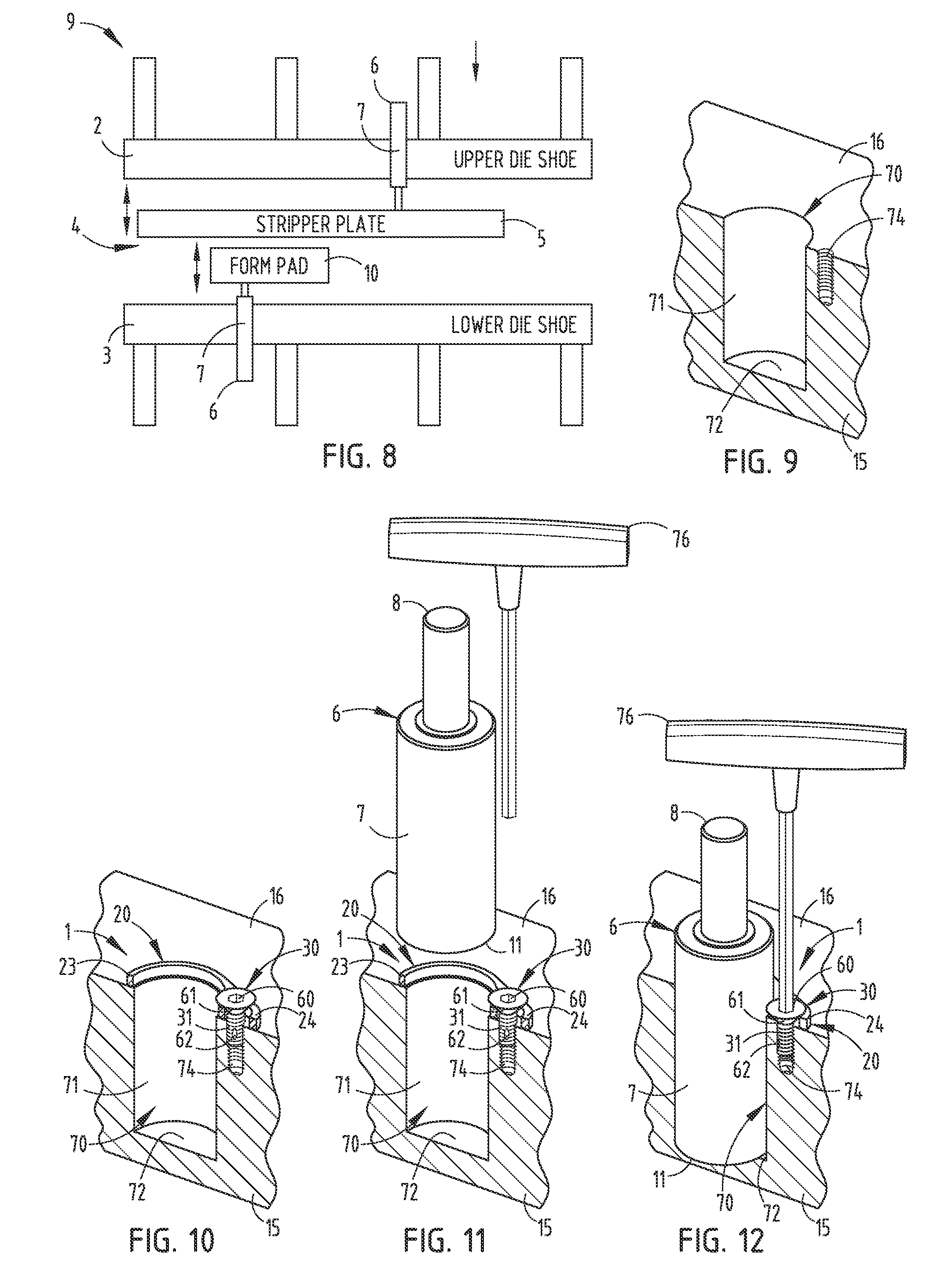
[0043]For purposes of description herein, the terms “upper,”“lower,”“right,”“left,”“rear,”“front,”“vertical,”“horizontal” and derivatives thereof shall relate to the invention as oriented in FIGS. 1-7. However, it is to be understood that the invention may assume various alternative orientations and step sequences, except where expressly specified to the contrary. It is also to be understood that the specific devices and processes illustrated in the attached drawings, and described in the following specification, are simply exemplary embodiments of the inventive concepts defined in the appended claims. Hence, specific dimensions and other physical characteristics relating to the embodiments disclosed herein are not to be considered as limiting, unless the claims expressly state otherwise.

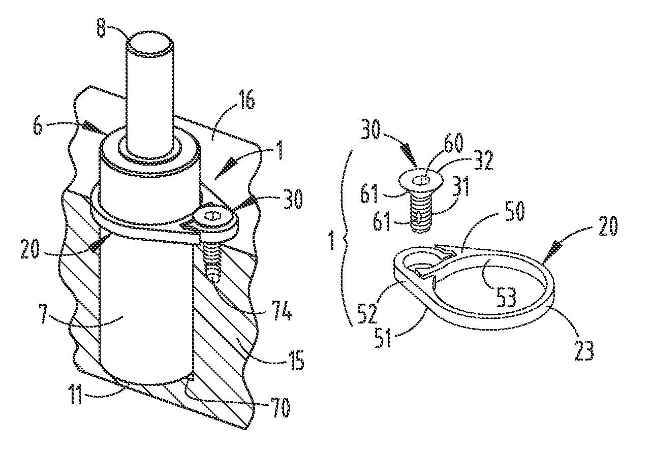
[0044]The reference numeral 1 (FIGS. 1-7) generally designates a gas spring retainer assembly embodying the present invention. Gas spring retainer assembly 1 is particularly adapted for use in conju...


PUM

PropertyMeasurementUnit
diameteraaaaaaaaaa
diameteraaaaaaaaaa
thicknessaaaaaaaaaa

Abstract

A gas spring mount and related method for metal forming dies includes a one-piece, split clamping ring having a generally ovate plan shape with two spaced apart axes of symmetry. A generally circular clamping portion extends around the first axis, and is shaped to receive a gas spring body therein. A hook-shaped end extends around the second axis, and is shaped to receive a tapered head mounting member therein. A resilient free end is located operably between the clamping portion and the hook-shaped end portion, whereby tightening of the mounting member shifts the hook-shaped end outwardly and the free end inwardly to constrictingly pull the clamping ring securely against the gas spring body, and contemporaneously attach the assembly to an associated die member.

Description

CROSS REFERENCE TO RELATED APPLICATION AND CLAIM TO PRIORITY[0001]The present application is related to commonly assigned, copending U.S. patent application Ser. No. 13 / 331,276, filed even date herewith, entitled GAS SPRING MOUNTING ASSEMBLY AND METHOD FOR METAL FORMING DIES, which is hereby incorporated herein by reference.[0002]Applicants hereby claim the priority benefits under the provisions of 35 U.S.C. §119, basing said claim of priority on related Provisional Patent Application Ser. No. 61 / 425,372, filed Dec. 21, 2010.BACKGROUND OF THE INVENTION[0003]The present invention relates to metal forming dies the like, and in particular to a gas spring mounting assembly and associated method.[0004]Metal forming dies, such as stamping dies and the like, are well known in the art. Progressive metal forming dies are unique, very sophisticated mechanisms which have multiple stations or progressions that are aligned longitudinally, and are designed to perform a specified operation at each...

Claims


Application Information

Patent Timeline
Patent Type & Authority Patents(United States)
IPC IPC(8): B21J9/18B21D45/00B21D43/05
CPCF16B2/08B21K5/20B21J13/02Y10T83/8785Y10T403/56Y10T29/49826
Inventor BREEN, SCOTT M.PYPER, JOEL T.
Owner STANDARD LIFTERS INC
Why Eureka
Try Eureka