Compact and robust load and moment sensor

a sensor and load technology, applied in the field of compact and robust sensors, can solve the problems of difficult design of compact sensors to measure both applied loads and applied moments, easy damage to components, and difficult to measure both strains in the same sensor, so as to improve the functional life of load and moment sensors, improve the effect of high strength materials and easy replacemen

Active Publication Date: 2014-06-10
PROTEOR USA LLC
View PDF14 Cites 6 Cited by
  • Summary
  • Abstract
  • Description
  • Claims
  • Application Information

AI Technical Summary

Benefits of technology

[0009]The present invention relates to a compact and robust load and moment sensor for detecting loads applied to the sensor in a single direction and moments applied to the sensor in a single plane. This allows for load and moment detection in a compact sensor which can be modular. The modularity of the load and moment sensor allows for it to be replaced easily if it is damaged. Furthermore, the modularity allows for the load and moment sensor to be formed from a high strength material such as steel with minimal impact on the device's overall weight. The high strength material can improve the functional life of the load and moment sensor.
[0010]The load and moment sensor of the present invention includes a plurality of strain gauges placed on specific locations of a sensing element of the sensor. The plurality of strain gauges are wired together into resistor circuits such as two Wheatstone bridges. The output of one Wheatstone bridge is proportional to the applied load while the output of the other is proportional to the applied moment. While the strain gauges can be located, for example, on a single sensing element, some of the resistive elements of the Wheatstone bridges can be located elsewhere on the prosthetic leg. By intelligently placing the strain gauges on the single sensing element, and by using the Wheatstone bridges, more accurate information regarding the load in the single direction and the load in the single plane is received. That is, the combination of the location of the strain gauges and the use of the Wheatstone bridges allows for good side load rejection (which is load and / or moment not in the single direction or the single plane), good noise rejection, and good temperature compensation.
[0011]The good side load rejection, noise rejection, and temperature compensation can allow the prosthetic leg to more accurately mimic a human gait. Furthermore, the use of one Wheatstone bridge for applied load and another for applied moment improves performance of the prosthetic leg since a processor does not need to calculate the load and moment. The load and moment are measured directly from the outputs of the Wheatstone bridges.
[0012]In addition, the use of a single sensing element can reduce an amount of components utilized by the prosthetic leg. Since components are prone to be damaged, reducing a number of components also reduces an amount of objects which can be potentially damaged. This translates to a lower cost and greater reliability because there are less components that are prone to being damaged and which need to be replaced.
[0013]Also, the strain gauges can be semiconductor strain gauges which tend to have a smaller size while having a higher gauge factor. The higher gauge factor allows for the load and moment sensor to provide accurate results using low strains, which increases fatigue life and resistance to overloading of the load and moment sensor.
[0014]These improvements in the sensor can improve the functionality of the prosthetic leg such that it may have application to a broader cross section of the amputee population. The compact feature of the load and moment sensor of the present invention allows the prosthetic device to be used by amputees that are shorter in height, especially children, since the prosthetic device must be the same length as the intact limb of the amputee. Furthermore, the robustness of the load and moment sensor of the present invention allows the prosthetic device to be used both in harsher environments and in more aggressive activities such as construction, hiking, and various sports.

Problems solved by technology

In addition, designing a single, compact sensor to measure both an applied load and an applied moment presents a difficult challenge.
At a certain point, the strain induced by the applied load will be so small relative to the strain induced by the applied moment that it will become very difficult to measure both strains in the same sensor.
Since components are prone to be damaged, reducing a number of components also reduces an amount of objects which can be potentially damaged.

Method used


Image

  • Compact and robust load and moment sensor
  • Compact and robust load and moment sensor
  • Compact and robust load and moment sensor

Examples


Embodiment Construction

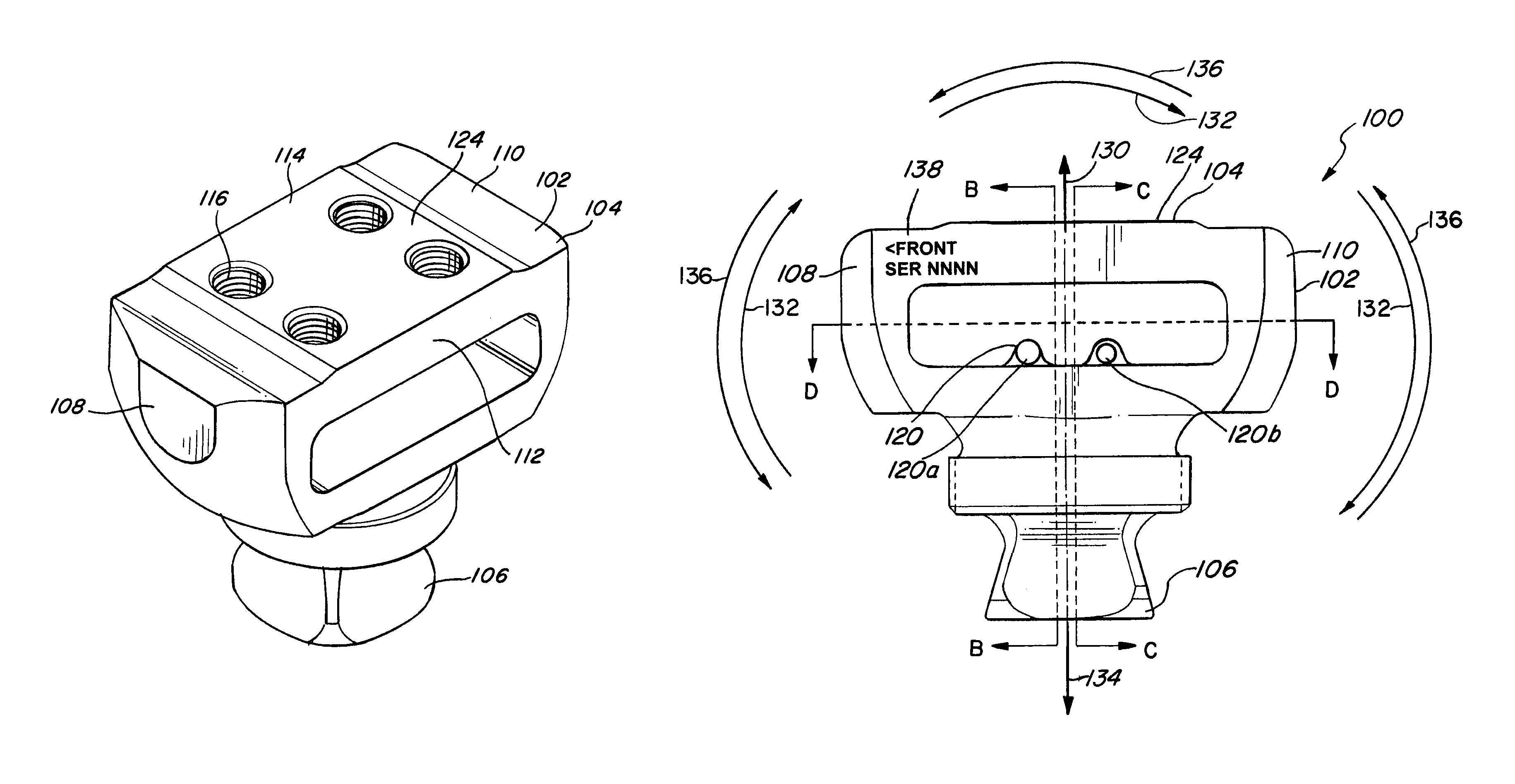
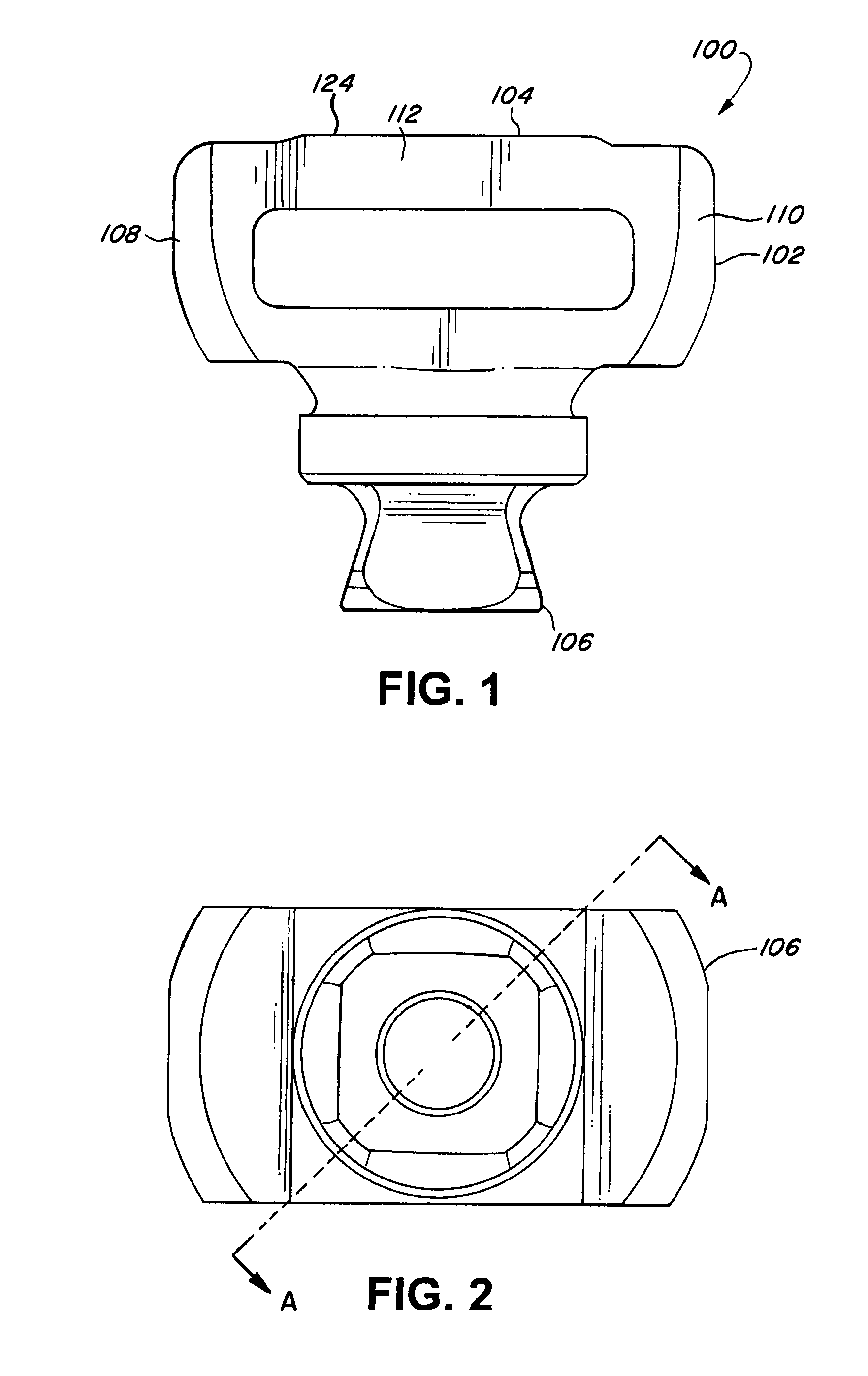
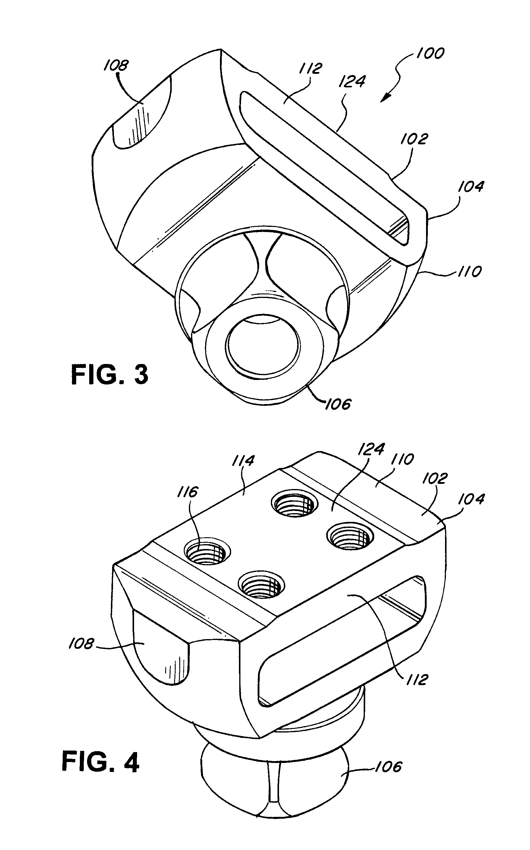
[0032]The detailed description of exemplary embodiments herein makes reference to the accompanying drawings and pictures, which show the exemplary embodiment by way of illustration and its best mode. While these exemplary embodiments are described in sufficient detail to enable those skilled in the art to practice the invention, it should be understood that other embodiments may be realized and that logical and mechanical changes may be made without departing from the spirit and scope of the invention. Thus, the detailed description herein is presented for purposes of illustration only and not of limitation. For example, the steps recited in any of the method or process descriptions may be executed in any order and are not limited to the order presented. Moreover, any of the functions or steps may be outsourced to or performed by one or more third parties. Furthermore, any reference to singular includes plural embodiments, and any reference to more than one component may include a s...


PUM

PropertyMeasurementUnit
voltageaaaaaaaaaa
differential voltageaaaaaaaaaa
lengthaaaaaaaaaa

Abstract

The present invention relates to a load and moment sensor for a prosthetic device detecting load in a single direction and moment in a single plane. The load and moment sensor includes a sensing element, and a plurality of strain gauges placed in specific locations of the sensing element. The plurality of strain gauges is part of a plurality of resistor circuits such as Wheatstone bridges. While the strain gauges can be located on a single sensing element, some resistive elements of the Wheatstone bridges can be located elsewhere on the prosthetic device. The combination of the location of the strain gauges and the use of the Wheatstone bridges allows for good side load rejection which is load and moment not in the single direction or the single plane.

Description

CROSS-REFERENCES TO RELATED APPLICATIONS[0001]The present application claims the benefit of U.S. Provisional Application Ser. No. 61 / 304,367 filed on Feb. 12, 2010 entitled: “Compact and Robust Load and Moment Sensor,” which is hereby incorporated by reference in its entirety. The present application also incorporates by reference U.S. Pat. No. 7,655,050 and U.S. application Ser. No. 12 / 697,969, filed Feb. 1, 2010, each as if fully set forth herein.BACKGROUND[0002]1. Field of the Invention[0003]This disclosure relates to sensors for detecting loads and moments applied to the sensor, and more specifically to a compact and robust sensor for detecting loads applied to the sensor in a single direction and moments applied to the sensor in a single plane.[0004]2. Description of the Related Art[0005]Modern, computer-controlled prosthetic devices have many advantages over conventional prosthetic devices. For example, computer-controlled prosthetic devices can allow the amputees to walk with...

Claims


Application Information

Patent Timeline
Patent Type & Authority Patents(United States)
IPC IPC(8): G01L1/22
CPCG01L1/22A61F2/76A61F2002/7645A61F2/6607A61F2002/7635A61F2/64G01L5/161G01L1/2231G01L5/1627
Inventor PALMER, MICHAEL, L.
Owner PROTEOR USA LLC
Why Eureka
Try Eureka