
Vapor deposition reactor and method for forming thin film

a technology of vapor deposition reactor and thin film, which is applied in the direction of vacuum evaporation coating, coating, chemistry apparatus and processes, etc., can solve the problems of reducing reliability, excessive adsorption, and shortening the life of the valv

Inactive Publication Date: 2014-06-24
VEECO ALD
View PDF236 Cites 215 Cited by
  • Summary
  • Abstract
  • Description
  • Claims
  • Application Information

AI Technical Summary

Benefits of technology

This patent is for a type of vapor deposition reactor that works by adsorbing, desorbing, and externally exhausting a series of layers of material on a substrate. The reactor has multiple injection points and recesses that allow the materials to flow through and absorb onto the substrate. The reactor can have a lower pressure in the third recess to help the materials better absorb. The patent also includes an additional set of recesses that can be filled with different materials, allowing for more flexibility in the process. Overall, this reactor design allows for a more precise and efficient deposition of materials onto substrates.

Problems solved by technology

More specifically, a source precursor is injected into a chamber so that the source precursor is excessively adsorbed on a substrate.
As a result, the lifetime of the valve is shortened, and its reliability is decreased.
As the number of operation times of the valve operated at a high speed is increased, problems related to the lifetime of the valve occur, such as erroneous operations or particles.
Also, a large amount of precursor is required because a sufficient amount of precursor is necessarily filled in the interior of the chamber for the purpose of saturation adsorption of precursors on a surface of the substrate.
Therefore, much time is taken to perform sufficient purging and / or pumping to prevent the source precursors or reactant precursors from remaining in the chamber.
Therefore, the reliability, durability and economy of the device are decreased as well as yielding thinner film.
Hence, its structure is complicated.
In addition, since the partitions serve as only physical barriers for isolating the ports from each other, there is a structural limitation in that pumping ports are necessarily positioned at both sides (or left and right sides) of each of the ports through which the precursors are injected or purged.

Method used


Image

  • Vapor deposition reactor and method for forming thin film
  • Vapor deposition reactor and method for forming thin film
  • Vapor deposition reactor and method for forming thin film

Examples


Embodiment Construction

[0052]Exemplary embodiments now will be described more fully hereinafter with reference to the accompanying drawings, in which exemplary embodiments are shown. This disclosure may, however, be embodied in many different forms and should not be construed as limited to the exemplary embodiments set forth therein. Rather, these example embodiments are provided so that this disclosure will be thorough and complete, and will fully convey the scope of this disclosure to those skilled in the art. In the description, details of well-known features and techniques may be omitted to avoid unnecessarily obscuring the presented embodiments.

[0053]The terminology used herein is for the purpose of describing particular embodiments only and is not intended to be limiting of this disclosure. As used herein, the singular forms “a”, “an” and “the” are intended to include the plural forms as well, unless the context clearly indicates otherwise. Furthermore, the use of the terms a, an, etc. does not deno...


PUM

PropertyMeasurementUnit
distanceaaaaaaaaaa
thicknessaaaaaaaaaa
depthaaaaaaaaaa

Abstract

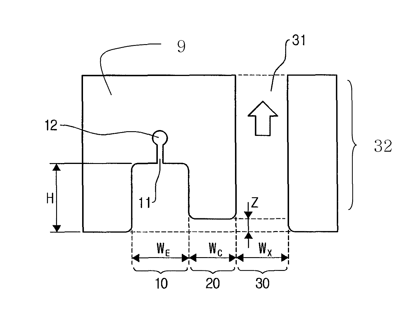
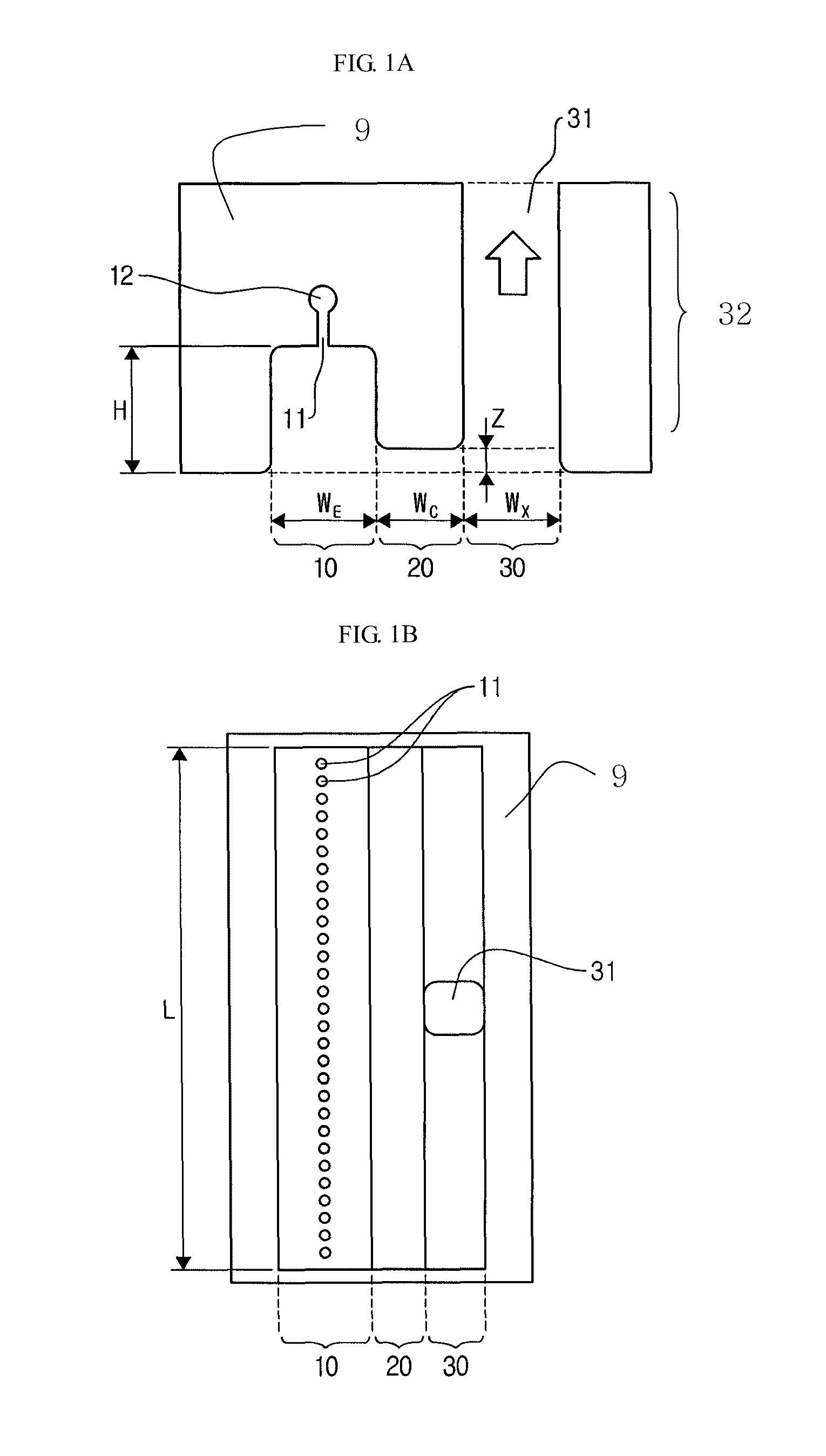
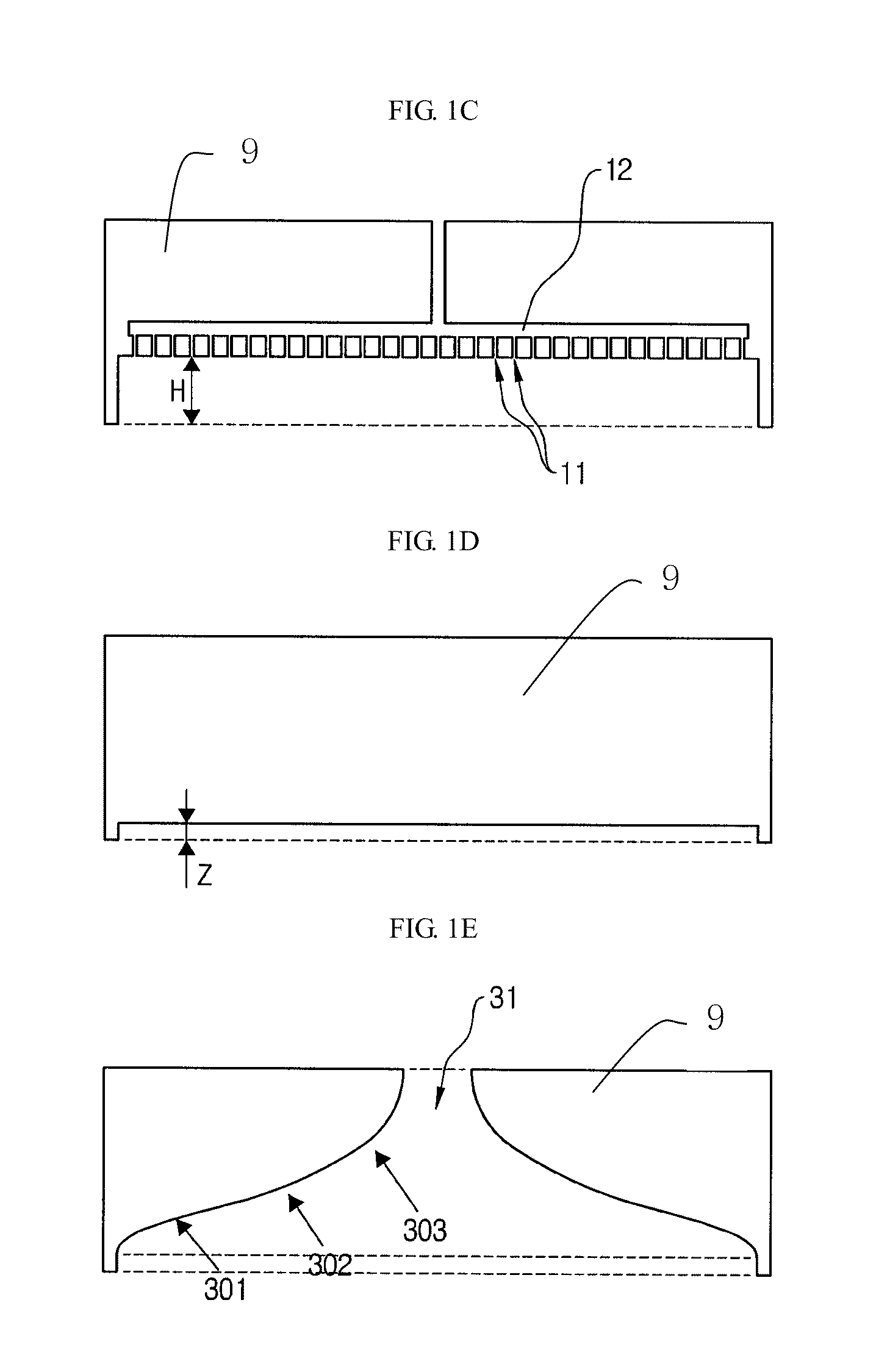
A vapor deposition reactor and a method for forming a thin film. The vapor deposition reactor includes at least one first injection portion for injecting a reacting material to a recess in a first portion of the vapor deposition reactor. A second portion is connected to the first space and has a recess connected to the recess of the first portion. The recess of the second portion is maintained to have pressure lower than the pressure in the first space. A third portion is connected to the second space, and an exhaust portion is connected to the third space.

Description

CROSS-REFERENCE TO RELATED APPLICATION[0001]This application claims priority from and the benefit under 35 U.S.C. §119(e) of U.S. Patent Application No. 61 / 185,076, entitled “Reactor Apparatus For Atomic Layer Deposition And Method Of Forming Thin Film Using The Reactor Apparatus,” filed on Jun. 8, 2009, which is incorporated by reference herein in its entirety. This application is related to U.S. patent application Ser. No. 12 / 539,477, entitled “Vapor Deposition Reactor For Forming Thin Film,” filed on Aug. 11, 2009; U.S. patent application Ser. No. 12 / 539,490, entitled “Vapor Deposition Reactor,” filed on Aug. 11, 2009; and U.S. patent Ser. No. 12 / 560,690, entitled “Vapor Deposition Reactor Using Plasma And Method for Forming Thin Film Using the Same,” filed on Sep. 16, 2009, which are incorporated by reference herein in their entirety.BACKGROUND[0002]1. Field of the Invention[0003]The disclosure relates to a vapor deposition reactor and a method for forming a thin film using the ...

Claims


Application Information

Patent Timeline
Patent Type & Authority Patents(United States)
IPC IPC(8): C23C16/00
CPCC23C16/40C23C16/34C01B21/076C23C16/45551C23C16/32C23C16/44C23C16/50H01L21/0262
Inventor LEE, SANG, IN
Owner VEECO ALD
Learn More