Thermally conductive foam product

a technology of thermal conductivity and foam, which is applied in the direction of semiconductor/solid-state device details, lighting and heating apparatus, medical instruments, etc., can solve the problems of increasing the complexity of the design, increasing the size of the device, and increasing the complexity of the circuit design of modern electronic devices, so as to improve the heat transfer effect of the electronic device, improve the thermal conductivity, and facilitate the preparation

Active Publication Date: 2014-06-24
PARKER INTANGIBLES LLC
View PDF16 Cites 24 Cited by
  • Summary
  • Abstract
  • Description
  • Claims
  • Application Information

AI Technical Summary

Benefits of technology

[0019]The compressible thermal interface foam pads of the present invention can be conveniently prepared from a solid foam pad by punching a plurality of vias completely through the pad with a cutting tool or die, and subsequently removing the chads. Alternatively, the plurality of vias can be molded into the pad during the pad manufacturing operation. Other methods for preparing the pads of the present invention will be readily apparent to those skilled in the art. Since the pad is compressible, it readily conforms to the first and second heat transfer surfaces, whether these surfaces are regular or irregular in shape. As the pad is compressed, the thermal conductivity increases, thereby enhancing the heat transfer from the electronic device to the heat sink.

Problems solved by technology

Conventional circuit designs for modern electronic devices such as televisions, radios, computers, medical instruments, business machines, communications equipment, and the like have become increasingly complex.
Although the complexity of the designs has increased, the size of the devices has continued to shrink with improvements in the ability to manufacture smaller electronic components and to pack more of these components in an ever smaller area.
In recent years, electronic devices have become smaller and more densely packed.
Designers and manufacturers are now facing the challenge of dissipating the heat generated in these devices using various thermal management systems.
The greases and waxes of the aforementioned types generally are not self-supporting or otherwise form-stable at room temperature, and are considered to be messy to apply to the interface surface of the heat sink or electronic component.
Moreover, the use of such materials typically involves hand application or lay-up by the electronics assembler which increases manufacturing costs.

Method used


Image

  • Thermally conductive foam product
  • Thermally conductive foam product

Examples


example

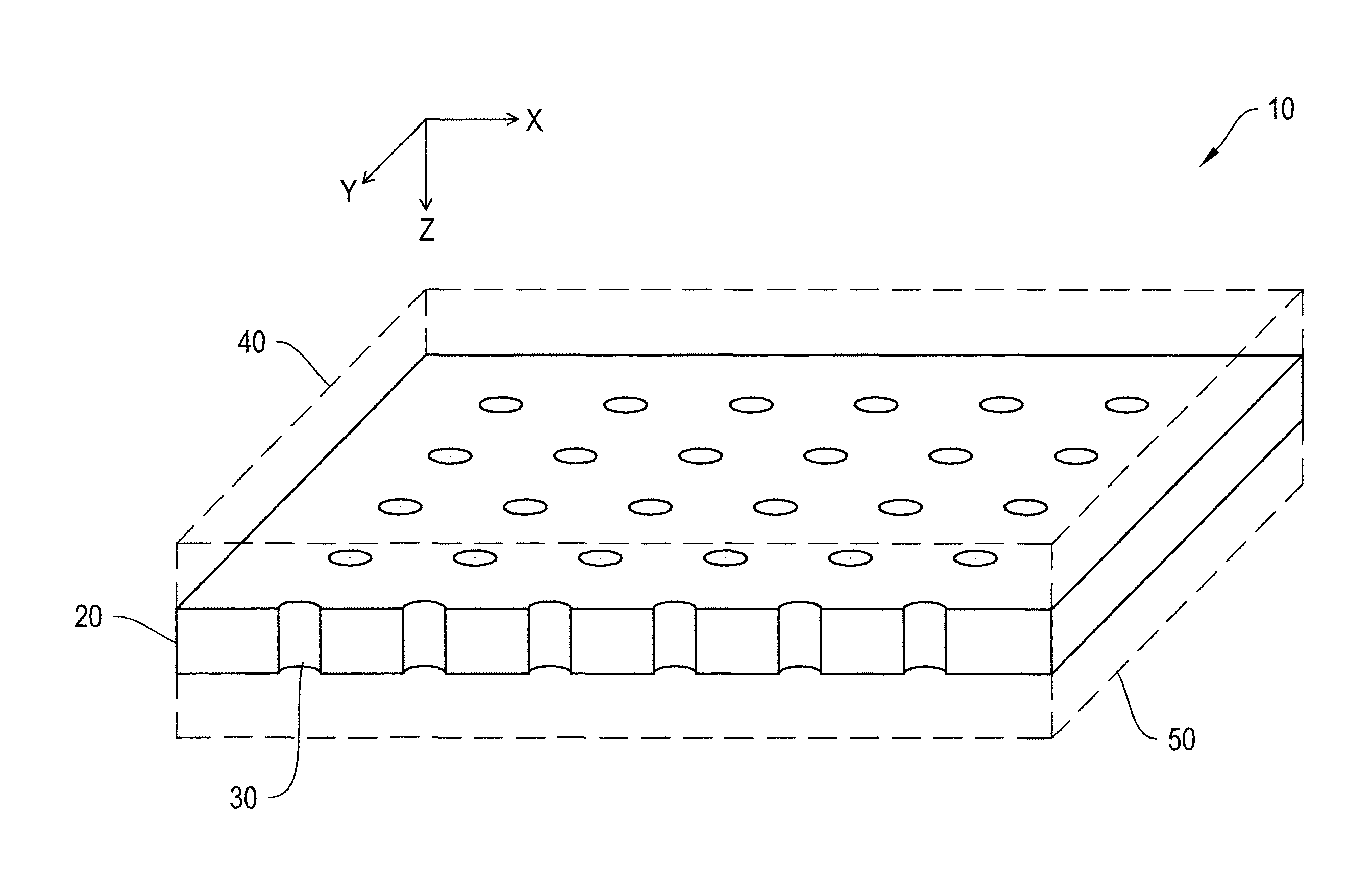
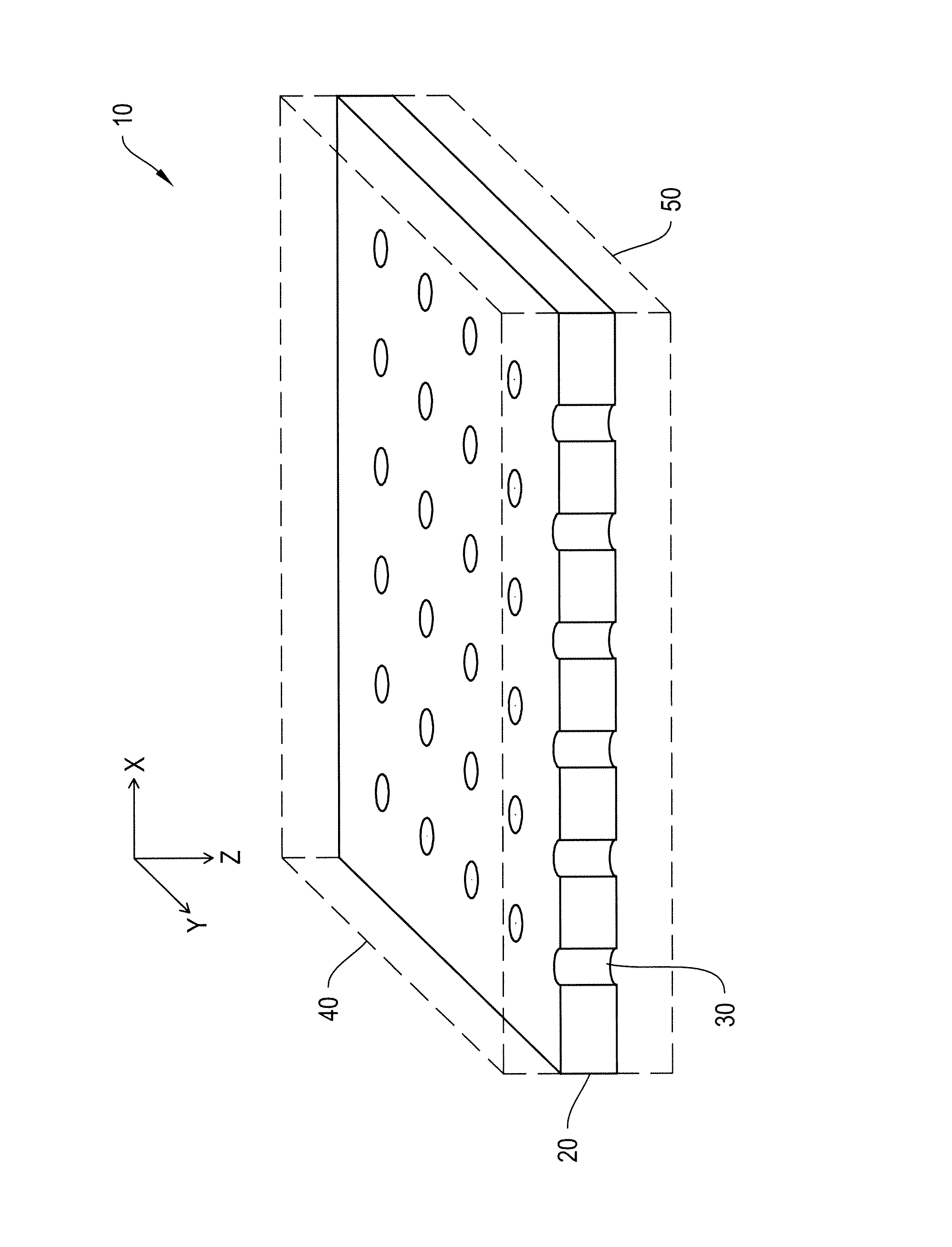
[0042]A foam interface pad was prepared as follows. A THERM-A-GAP™ G579 product, manufactured and sold by the Chomerics division of Parker Hannifin Corporation, was evaluated for thermal conductivity at two thicknesses: 0.070 inches and 0.130 inches. A 0.070 hole punch was used to punch holes in the samples. Two different hole patterns were used. The first pattern had holes every 0.25 inches in the X direction and every 0.5 inches in the Y direction. The second pattern had holes every 0.25 inches in both the X and Y directions.

[0043]The pads were then tested for thermal impedance per ASTM 5470 and compression deflection.

Results:

[0044]

Sample Blank Thickness Thermal Impedance Force to Deflect#Area(inches)(10 PSI) in{circumflex over ( )}2C / W50% (lbs)1~200.0701.0382~400.0701.0263~200.1301.5314~400.1301.625


PUM

PropertyMeasurementUnit
diameteraaaaaaaaaa
thicknessaaaaaaaaaa
densityaaaaaaaaaa

Abstract

A compressible, thermally conductive foam interface pad is adapted for emplacement between opposed heat transfer surfaces in an electronic device. One heat transfer surface can be part of a heat-generating component of the device, while the other heat transfer surface can be part of a heat sink or a circuit board. An assembly including the foam interface pad and the opposed electronic components is also provided.

Description

CROSS-REFERENCE TO RELATED APPLICATIONS[0001]This application is a national phase application of PCT / US2010 / 033684, filed May 5, 2010, which claims the benefit of U.S. Provisional Application No. 61 / 175,501, filed on May 5, 2009, the disclosures of which are incorporated herein by reference.BACKGROUND OF THE INVENTION[0002]The present invention relates to a compressible, thermally conductive interface foam product adapted to be disposed between two heat transfer surfaces, such as an electronic component and a heat sink, to provide a thermal pathway between the surfaces. The thermally conductive foam interface product comprises a layer of a cured elastomeric material having air-filled voids passing at least partially through the interface, and a thermally-conductive particulate filler dispersed in the cured product. A thermal management assembly comprising the interface product and the two heat transfer surfaces is also provided. Preferably, the interface material is a silicone pad w...

Claims


Application Information

Patent Timeline
Patent Type & Authority Patents(United States)
IPC IPC(8): B32B5/22B32B3/10
CPCY10T428/24273H01L23/3733H01L2924/3011H01L23/433H01L2924/0002Y10T428/249975Y10T428/249986H01L23/3737H01L2924/00
Inventor BERGIN, JONATHANSANTA FE, VICTORIASEVERANCE, CHRISTOPHERROSA, GARY
Owner PARKER INTANGIBLES LLC
Why Eureka
Try Eureka