
Spark-over prevention device for high-voltage bushing

a high-voltage bushing and prevention device technology, which is applied in the direction of coupling device connections, electrical apparatus casings/cabinets/drawers, insulating bodies, etc., can solve the problems of high-voltage bushing failure, large potential difference between adjacent positions on the bushing tube and the draw-lead cable, and bushing tube failure, etc., to prevent spark-over and eliminate the effect of spark-over

Active Publication Date: 2014-06-24
HUBBELL INC
View PDF10 Cites 7 Cited by
  • Summary
  • Abstract
  • Description
  • Claims
  • Application Information

AI Technical Summary

Benefits of technology

This patent text describes a high-voltage bushing with a spark-over prevention device that prevents electrical spark-overs between the bushing and the neighboring components. The device includes a tube, a conductor, and an electrically conductive contact member. The contact member is connected to the tube and has a first opening to receive and contact the conductor. This prevents spark-over that may occur between the inner surface of the tube and the outer surface of the draw-lead cable. The invention also includes a method of assembling a high-voltage bushing with the same features. Overall, this patent aims to improve the reliability and safety of high-voltage systems.

Problems solved by technology

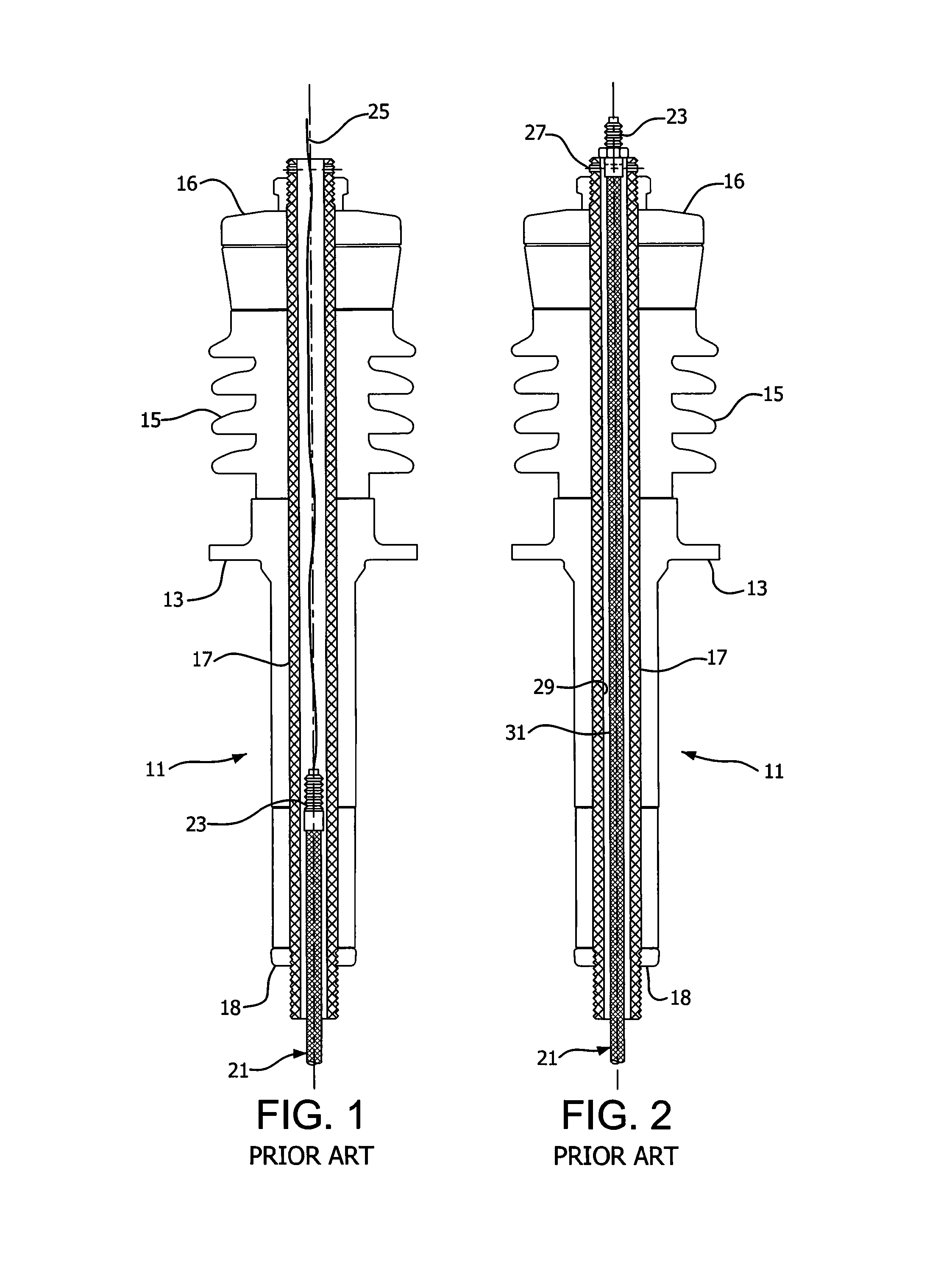
However, the bottom of the draw-lead cable or rod does not have full contact with the bushing tube, especially when the draw-lead cable is insulated.
One problem associated with a high-voltage bushing is spark-over, or arcing, between the draw-lead cable conductor and the inner surface of the hollow tube of the bushing through which the conductor passes, thereby resulting in failure of the bushing.
Two causes of high-frequency transients are lightning induced insulator spark-overs and circuit switching.
The split waves travel along the two separate paths with different speeds and reflect differently, thereby creating a large potential difference between the adjacent positions on the bushing tube and the draw-lead cable.
The large potential difference results in the arcing or spark-over between the two bushing tube and the draw-lead cable, thereby resulting in failure of the high-voltage bushing.
These failures are often explosive and can result in fires.
Additional insulation has been added to the draw-lead cable to prevent spark-over, but has not proved effective.

Method used


Image

  • Spark-over prevention device for high-voltage bushing
  • Spark-over prevention device for high-voltage bushing
  • Spark-over prevention device for high-voltage bushing

Examples


Embodiment Construction

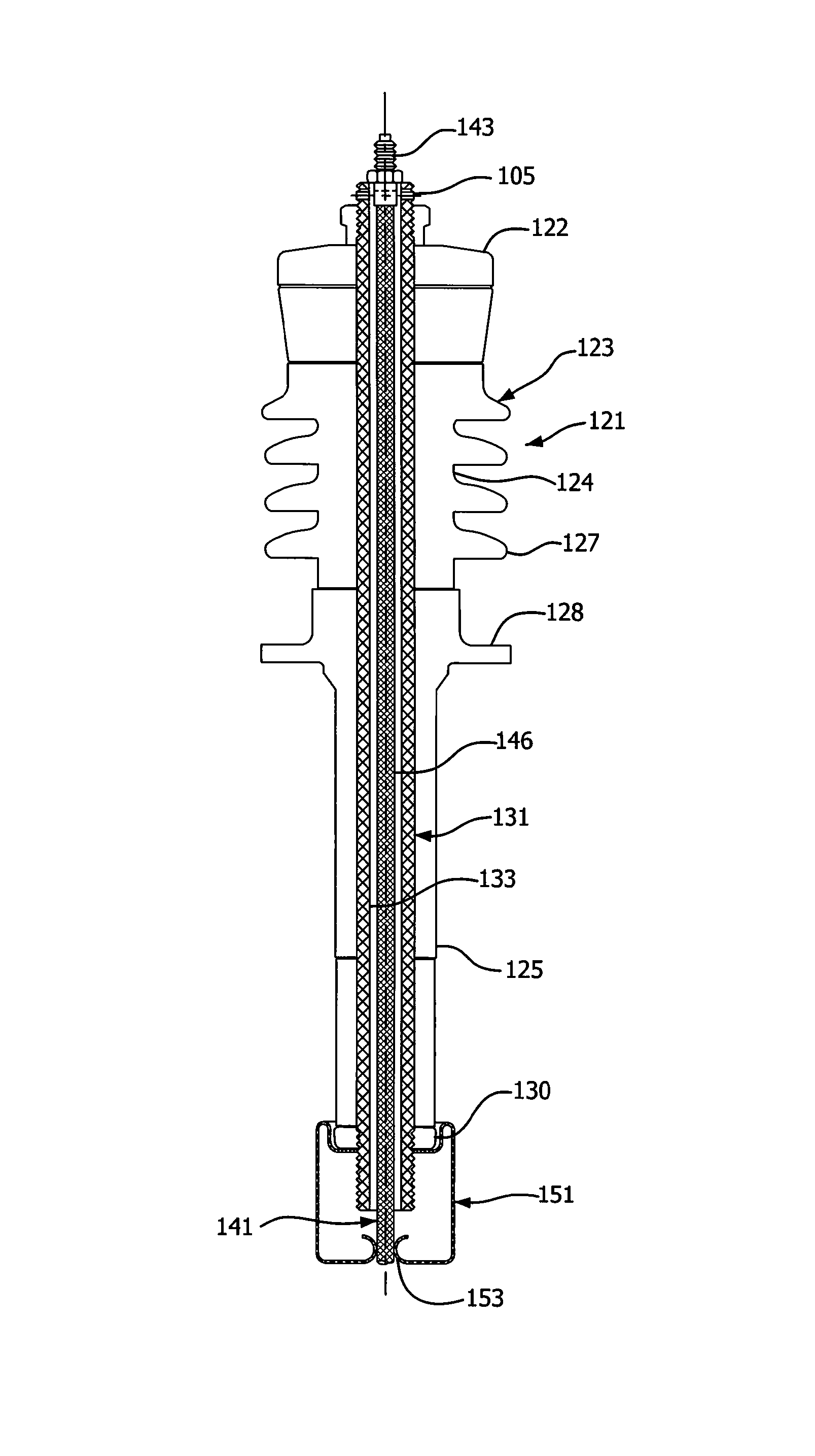
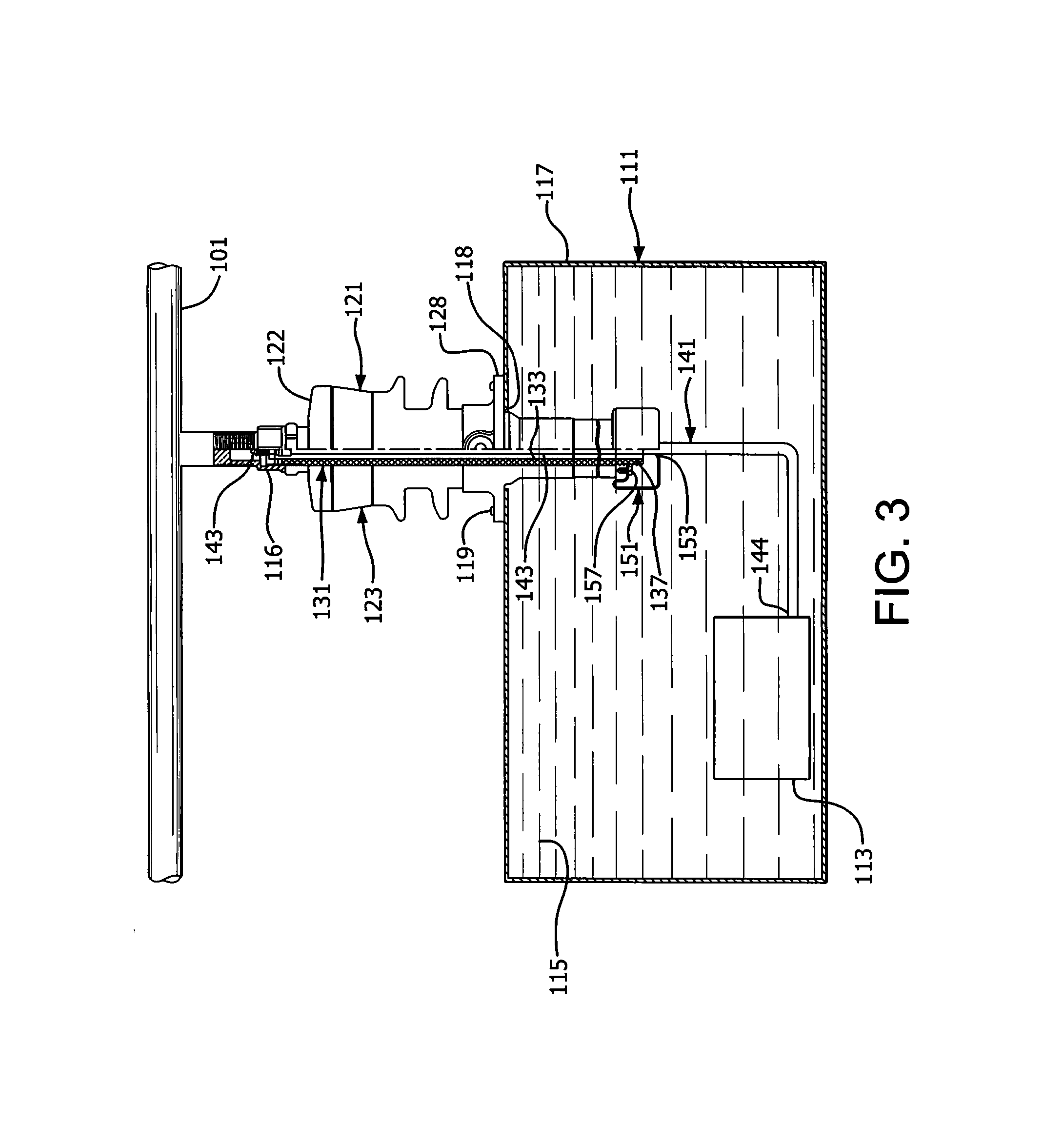
[0034]As shown in FIGS. 3-8, an exemplary embodiment of the present invention includes a spark-over prevention device 151 for a high-voltage bushing 121. An electrically conductive tube 131 is disposed within an electrically insulating housing 123 of the high-voltage bushing 121. A conductor 141 is disposed within the tube 131. The spark-over prevention device is a metallic contact member 151 is connected to the tube 131 and has a first opening 153 to receive and directly contact the conductor 141. Accordingly, spark-over between the inner surface 133 of the tube 131 and the outer surface 143 of the draw-lead cable 141 caused by a high-frequency transient is substantially prevented.

[0035]As described above, the draw-lead high-voltage bushing 121 in accordance with exemplary embodiments connects a winding, or draw-lead, cable 141 from a transformer coil and core assembly 113 to a power line 101, as shown in FIG. 3. The core 113 is immersed in oil 115 within a housing 117 of the trans...


PUM

PropertyMeasurementUnit
voltageaaaaaaaaaa
voltageaaaaaaaaaa
electrically conductiveaaaaaaaaaa

Abstract

A high-voltage bushing includes a housing and a tube disposed within the housing. A conductor is disposed within the tube. An electrically conductive contact member is connected to the tube and has a first opening to receive and contact the conductor. Accordingly, spark-over between the inner surface of the tube and the outer surface of the draw-lead cable caused by a high-frequency transient is substantially prevented.

Description

FIELD OF THE INVENTION[0001]The present invention relates to a spark-over prevention device for a high-voltage bushing. More particularly, the present invention relates to a spark-over prevention device for a draw-lead high-voltage bushing. Still more particularly, the present invention relates to an electrically conductive contact member connected to a draw-lead cable and a bushing tube substantially eliminating a potential difference between the draw-lead cable and the draw-lead tube to substantially prevent spark-over therebetween.BACKGROUND OF THE INVENTION[0002]Electricity is transferred through electrical power systems at high-voltage levels of typically 15 kV to 500 kV. A power transformer steps up and down the voltages. A high-voltage bushing is the interface between the transformer winding and external power lines.[0003]The high-voltage bushing is a hollow insulator through which a conductor passes. Each end of the conductor is connected to electrical equipment. For example...

Claims


Application Information

Patent Timeline
Patent Type & Authority Patents(United States)
IPC IPC(8): H01B17/26H01B17/00H01B17/54H01B17/58H02G3/18
CPCH01R13/53H01B17/26H01B17/42H01F27/04H01R43/20Y10T29/49169
Inventor KO, CHUNGDUCKZHANG, SHIBAOWEATHERBEE, ERIC R.MCNULTY, ANDREW V.CIRKOVIC, KATA
Owner HUBBELL INC
Learn More