Implementing DC motor positive and negative rotation circuit by PLC-controlled relay
A technology for controlling relays and DC motors, which is applied to the starter, motor generator/starter, starter parts, etc. of a single DC motor. It is easy to burn out and other problems, so as to reduce the impact and prolong the life.
- Summary
- Abstract
- Description
- Claims
- Application Information
AI Technical Summary
Problems solved by technology
Method used
Image
Examples
Embodiment Construction
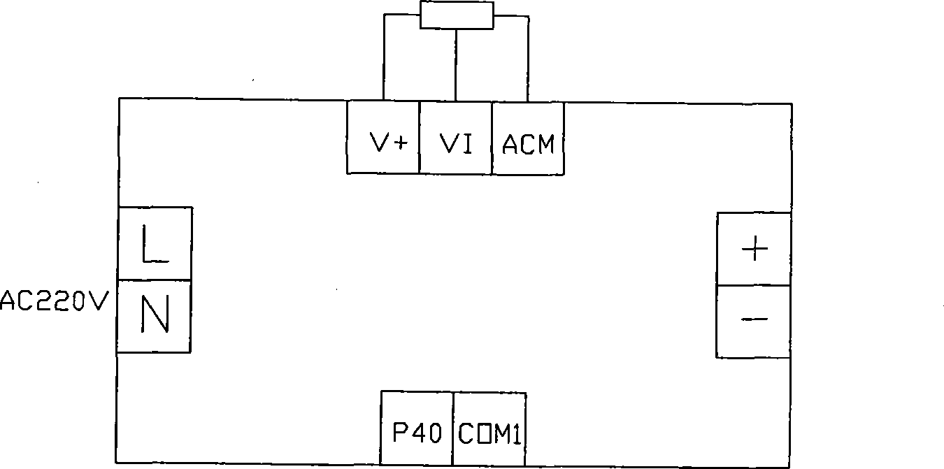
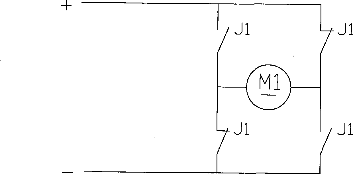
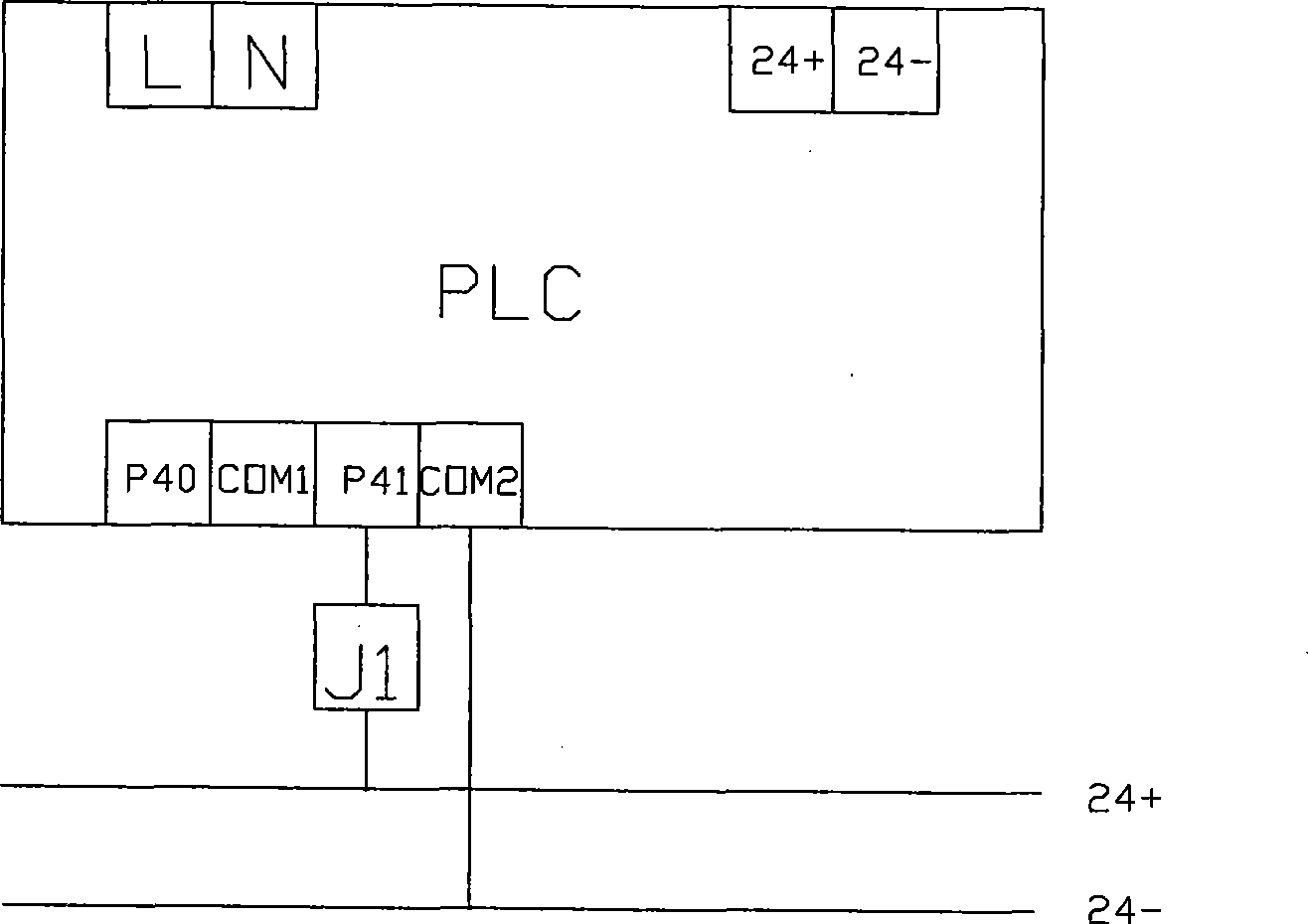
[0017] Such as figure 1 Shown: the AC power supply is connected with the DC speed control power supply U1 and the interfaces L and N of the single-chip PLC, the DC speed control power supply U1 is connected with the relay J1, the relay J1 is connected with the DC motor M1, and the interfaces P40 and COM1 of the DC speed control power supply U1 are connected with The corresponding interface P40 and COM1 of the single-chip PLC are connected, and the relay J1 is connected with the interface P41 of the single-chip PLC.
[0018] Working process of the present invention:
[0019] Direct rotation of DC motor M1: The single-chip PLC issues an instruction to first close the control relay J1, and after 0.2 seconds, the single-chip PLC issues an instruction to start the DC speed control power supply U1, and the DC motor M1 begins to rotate forward.
[0020] DC motor M1 stops: the single-chip PLC issues an instruction to first disconnect the DC speed control power supply U1, and after 0....
PUM
 Abstract
Description
Claims
Application Information
 - R&D
- Intellectual Property
- Life Sciences
- Materials
- Tech Scout
- Unparalleled Data Quality
- Higher Quality Content
- 60% Fewer Hallucinations
Browse by: Latest US Patents, China's latest patents, Technical Efficacy Thesaurus, Application Domain, Technology Topic, Popular Technical Reports.
© 2025 PatSnap. All rights reserved.Legal|Privacy policy|Modern Slavery Act Transparency Statement|Sitemap|About US| Contact US: help@patsnap.com


