Vibration insulator for fuel injection valve, and support structure for fuel injection valve

a technology of vibration insulation and fuel injection valve, which is applied in the direction of noise reduction fuel injection, mechanical equipment, machines/engines, etc., can solve the problems of thermal deformation, various vibrations that accompany the operation of the internal combustion engine, and changes in relative positions of assembly, etc., to improve the reliability and stability of the support structure of the fuel injection valv

Active Publication Date: 2014-07-01
TOYOTA JIDOSHA KK +1
View PDF38 Cites 9 Cited by
  • Summary
  • Abstract
  • Description
  • Claims
  • Application Information

AI Technical Summary

Benefits of technology

[0006]According to the thus configured insulator, even when the axis of the fuel injection valve has deviated from the centered position between the insertion hole of the cylinder head and a delivery pipe in assembly, the first leg moves along the shoulder section of the insertion hole due to a force generated by the second leg, which flexes in accordance with the tapered stepped section of the fuel injection valve. This serves to appropriately compensate for the positional relations of the fuel injection valve with the insertion hole and the delivery pipe. On the other hand, when the internal combustion engine is operated, a high pressing force based on the above described fuel pressure presses the first leg and the second leg of the adjustment element against the shoulder section of the insertion hole and the tapered stepped section of the fuel injection valve, respectively, resulting in an increase of the frictional force between the shoulder section or the stepped section and the individual legs and a reduction of the position adjustment performance based on the movement of each leg as an adjustment element. That is, when the axis of the fuel injection valve is deviated from the centered position while the mobility of each leg has been reduced, a force that prevents such deviation may act. Specifically, the reactive force from each deformed leg in accordance with the pressing force applied to the adjustment element may press against the fuel injection valve. When such a force acts on the fuel injection valve, the above-described reduction of the sealing performance between the fuel injection valve and the delivery pipe by the O-ring may occur.

Problems solved by technology

Usually, when the fuel pressure supplied through the delivery pipe changes due to injection or stopping of the fuel, vibration based on the change in fuel pressure occurs to the above fuel injection valve.
Therefore, changes in the relative positions thereof, which are caused by, for example, tolerances associated with production or processing of these parts, tolerances associated with assembly in the production, thermal deformation, and various vibrations that accompany the operation of the internal combustion engine, are unavoidable.
Further, such positional deviation causes problems such as partial slack of an O-ring at the proximal end of the fuel injection valve, the O-ring serving to prevent fuel leakage between the fuel injection valve and the delivery pipe (fuel injection valve cup).
Therefore, the positional deviation may possibly cause fuel leakage.

Method used


Image

  • Vibration insulator for fuel injection valve, and support structure for fuel injection valve
  • Vibration insulator for fuel injection valve, and support structure for fuel injection valve
  • Vibration insulator for fuel injection valve, and support structure for fuel injection valve

Examples


first embodiment

[0050]A vibration insulator according to a first embodiment of the present invention will be described with reference to the drawings.

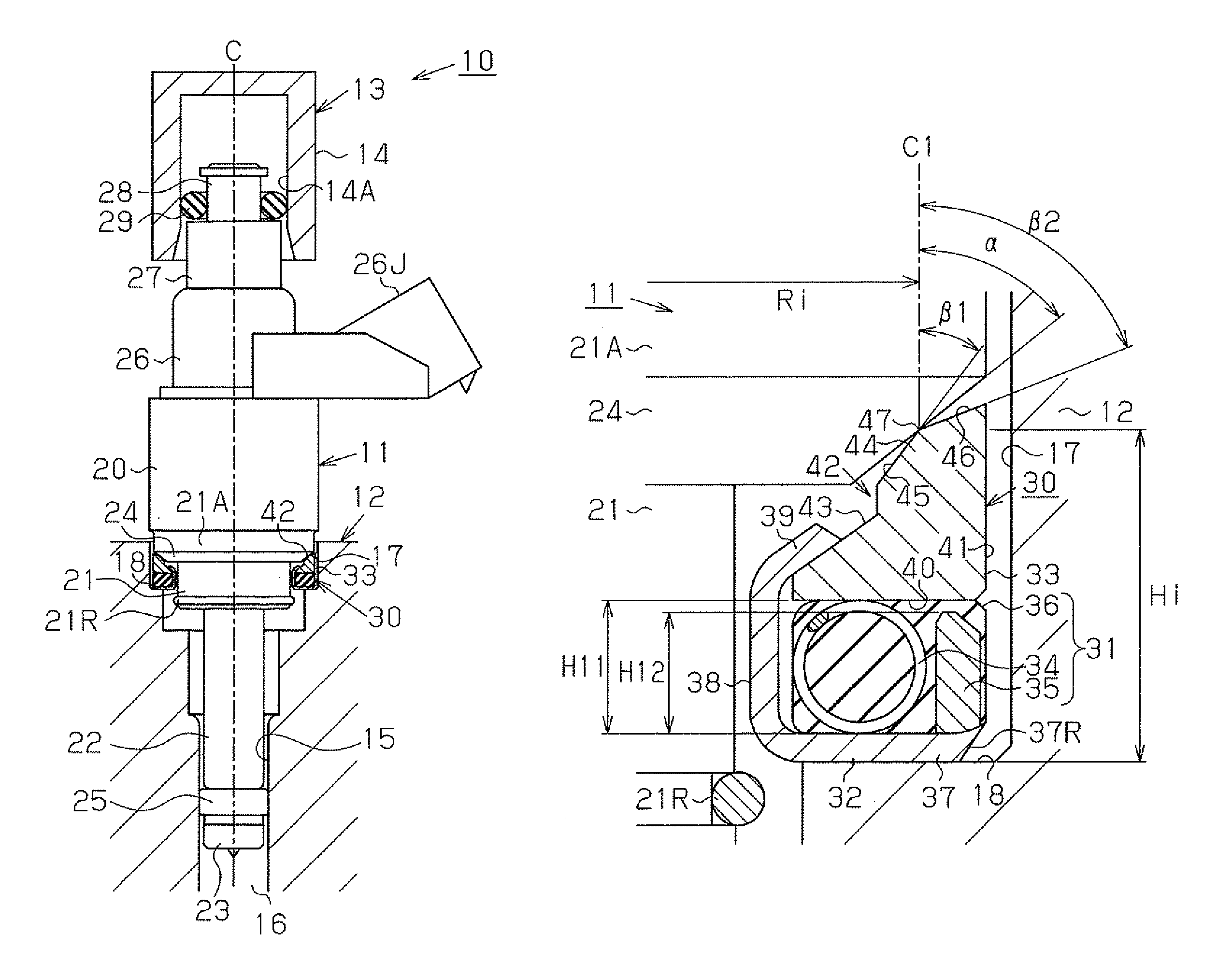
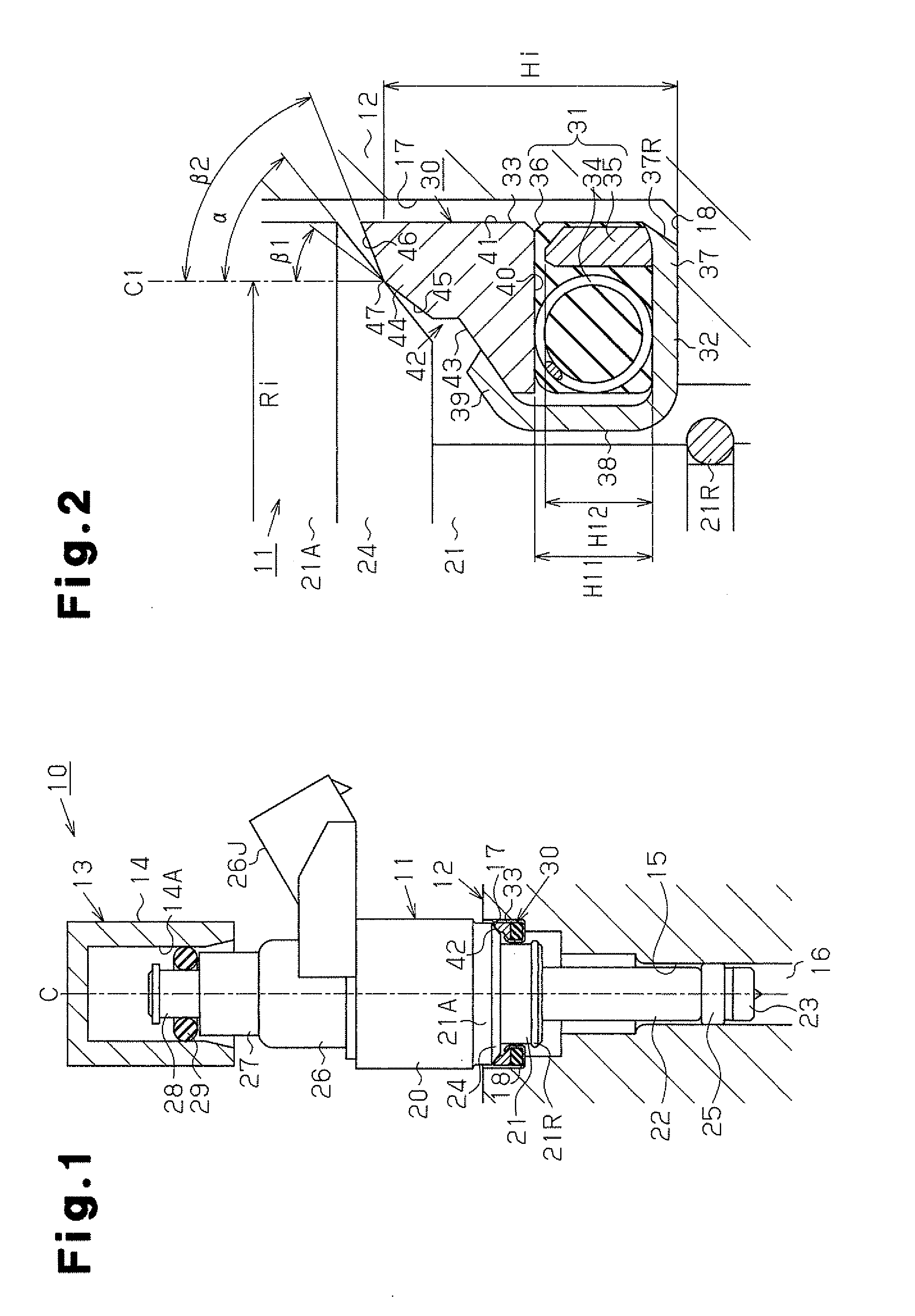
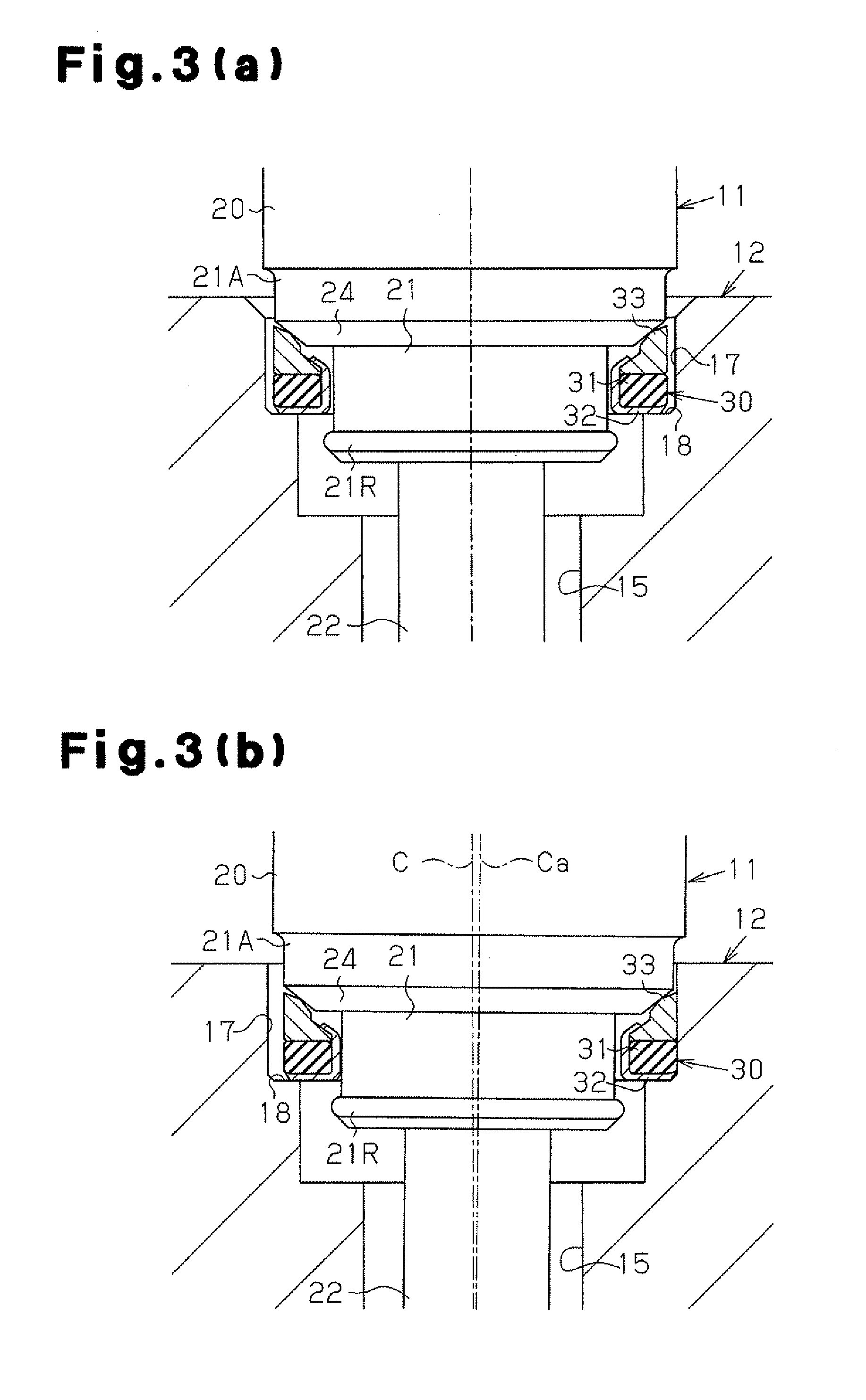
[0051]FIG. 1 is a diagram schematically showing the structure of a fuel injection system 10 to which a vibration insulator 30 according to this embodiment is applied. FIG. 2 is a diagram showing the structure of an end face of the vibration insulator 30 in an end view. FIGS. 3(a) and 3(b) are diagrams for illustrating the states of compensating for movement of the vibration insulator 30. FIG. 3(a) shows the fuel injection valve 11 in the state where the axis C thereof is not inclined.

[0052]As shown in FIG. 1, the fuel injection system 10 is provided with a fuel injection valve 11. A part of the fuel injection valve 11 in the distal end portion is supported by the insertion hole 15 of the cylinder head 12, and another part of the fuel injection valve 11 in the proximal end portion is supported by the fuel injection valve cup 14 of the delivery pipe 13....

second embodiment

[0099]FIG. 4 is an end view showing the structure of a vibration insulator 30 according to a second embodiment of the present invention. Since this embodiment differs from the first embodiment in structure of the tolerance ring of the vibration insulator 30 but the other structures are the same, differences from the first embodiment are mainly described, and description of members similar to those of the first embodiment is omitted by assigning the same reference signs thereto, for illustrative purposes.

[0100]As shown in FIG. 4, the vibration insulator 30 is formed by sequentially stacking a vibration damping member 31 and a tolerance ring 33A on a plate bottom section 37 of a plate 32.

[0101]The tolerance ring 33A, as in the case of the first embodiment, supports the fuel injection valve 11 by abutting the tapered surface 24 of the fuel injection valve 11 and is formed of metal such as stainless steel. Also, the tolerance ring 33A, as in the case of the first embodiment, includes th...

third embodiment

[0108]FIG. 5 is an end view showing the structure of a vibration insulator 30 according to a third embodiment of the present invention. Since this embodiment differs from the first embodiment in structure of the vibration damping member of the vibration insulator 30 but the other structures are the same, differences from the first embodiment are mainly described, and description of members similar to those of the first embodiment is omitted by assigning the same reference signs thereto, for illustrative purposes.

[0109]As shown in FIG. 5, the vibration insulator 30 is formed by sequentially stacking the vibration damping member 31B and the tolerance ring 33 on the plate bottom section 37 of the plate 32. The vibration damping member 31B is a member for absorbing and damping vibration of the fuel injection valve 11 and includes an elastic member 36 such as rubber, a coil spring 34 annularly embedded in the elastic member 36 and a sleeve 35B located from the coil spring 34 toward the i...


PUM


Abstract

A vibration insulator which can compensate for axial eccentricity occurring in a fuel injection valve and suppress vibrations of the valve during operation of a combustion engine and a support structure for the valve. The vibration insulator is interposed between a step height portion of the valve and a shoulder portion. The step height portion is increased in diameter in a tapered fashion and inserted into an insertion hole of a cylinder head. The shoulder portion is annularly extended in an inlet portion of the insertion hole opposed to the step height portion. The vibration insulator includes an annular tolerance ring on an inner circumferential inclined face thereof with recessed tapered faces opposed to the tapered face of the step height portion and which abuts the tapered face. The taper angles of the tolerance ring and of the step height portion are set so as to be different.

Description

FIELD OF THE DISCLOSURE[0001]The present invention relates to a vibration insulator for a fuel injection valve that is configured to damp vibration that occurs in the fuel injection valve, which injects fuel into an internal combustion engine, and to a support structure for a fuel injection valve using the vibration insulator.BACKGROUND OF THE DISCLOSURE[0002]Conventionally, internal combustion engines of one type in which fuel is injected into the inside of a combustion chamber, that is, internal combustion engines of the in-cylinder injection type, for example, have the distal end portion of a fuel injection valve inserted into and supported by an insertion hole of a cylinder head and have the proximal end portion of the fuel injection valve inserted into and supported by a delivery pipe (a fuel injection valve cup), whereby the fuel injection valve is provided across the cylinder head and the delivery pipe. Usually, when the fuel pressure supplied through the delivery pipe change...

Claims


Application Information

Patent Timeline
Patent Type & Authority Patents(United States)
IPC IPC(8): F01L3/20
CPCF02M61/14F02M2200/09F02M2200/858
Inventor SUGIYAMA, NATSUKISUMIDA, TOMOKAZUWATANABE, SEIZO
Owner TOYOTA JIDOSHA KK
Why Eureka
Try Eureka