
Trochanter retention plate

a retention plate and trochanter technology, applied in the field of trochanter retention plate, can solve the problems of irritating the tractus iliotibialis, bending open danger of arch-like prongs, and cutting of partly sharp-edged prongs

Active Publication Date: 2014-07-01
DURST HEIKO
View PDF10 Cites 15 Cited by
  • Summary
  • Abstract
  • Description
  • Claims
  • Application Information

AI Technical Summary

Benefits of technology

The present invention provides an implant and method for refixating the osteotomised or fractured trochanter major. The implant avoids the disadvantages of previous methods, and they neutralize abductor forces without significantly cutting into the bone substance of the trochanter major. The suitable materials for the implant include stainless steel, titanium, medical plastics, carbon, Kevlar, composite materials, and bioresorbable materials. Different combinations of these materials are possible and advantageous, such as a rigid distal plate shank and flexible at least one proximal plate prong.

Problems solved by technology

The lateral position directly above the tuberculum innominatum may then lead to the irritation of the tractus iliotibialis, which must slide over this region.
Moreover, with larger radii or with a course of the prong around the trochanter-major-fragment, there exists the danger of the arch-like prongs bending open, or, with osteoporotic bones, of the partly sharp-edged prongs cutting in.
Many of the mentioned implants have not displayed an adequate stability in clinical and / or biomechanical studies, or many of the mentioned implants suffered material failure in the course of dynamic loading.
The latter have the advantage that an operation for removal is done away with, but do not have an adequate stability for many applications.

Method used


Image

  • Trochanter retention plate
  • Trochanter retention plate
  • Trochanter retention plate

Examples


Embodiment Construction

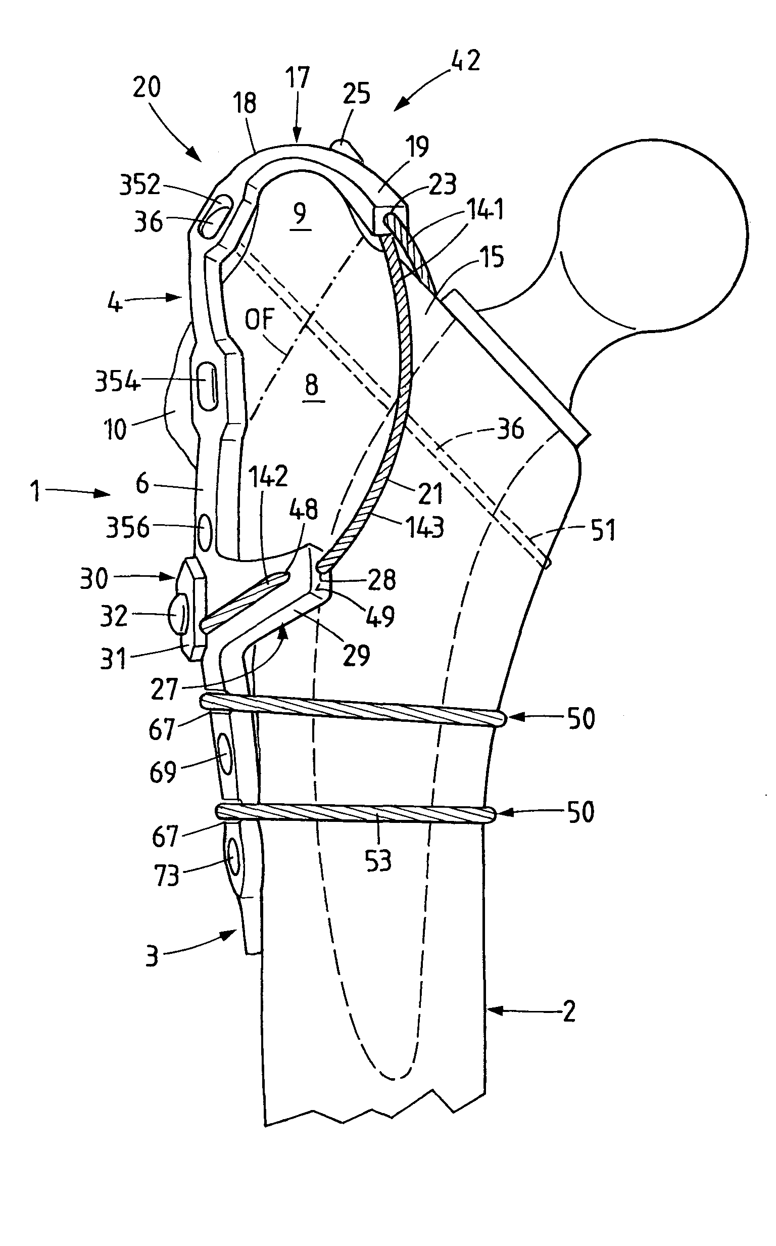
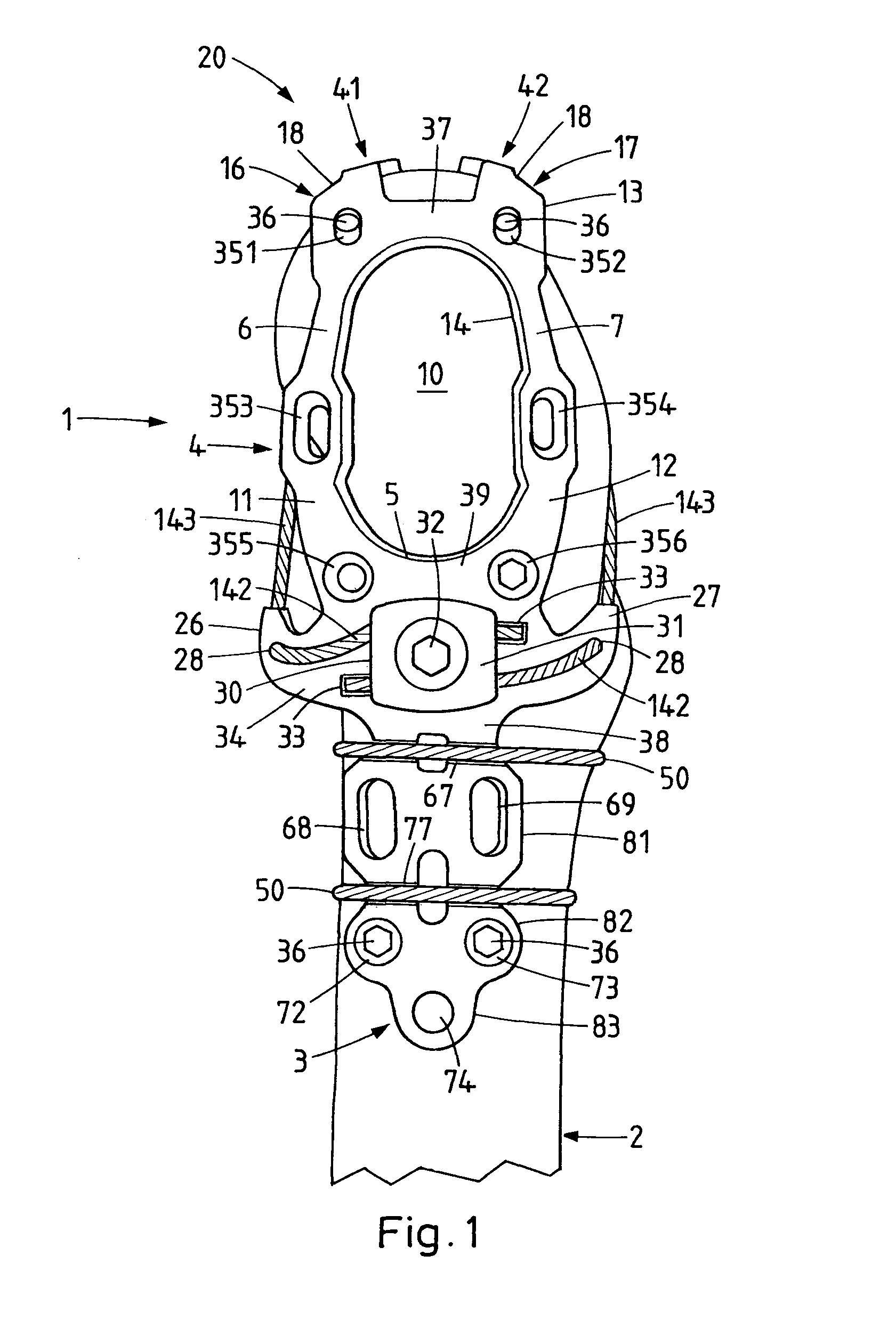
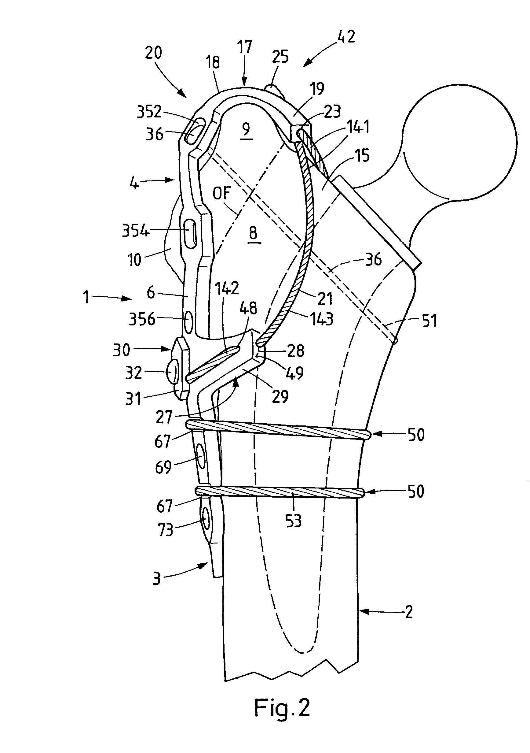
[0036]The trochanter retention plate which, as above and in the following, is also called implant for short, amongst other things serves for the anatomical reposition and stable fixation of the trochanter major 9 on the proximal femur 2 after osteotomy or fracture. An osteotomy plane or fracture plane of the trochanter major fragment is indicated in FIG. 2 at OF. The shown plane corresponds essentially to a standard osteotomy. With total osteotomy, the osteotomy line would define a plane, which, with an approximately equal starting point, would be led further distally. With a so-called extended trochanteric osteotomy (ETO), the osteotomy line would be led yet essentially further distally up to into the proximal femur.

[0037]In the shown embodiment example, the present invention is realised based on a tension band principle, with two retainers, which results from a combination of a laterally lying plate and medially lying retainers.

[0038]The implant according to a first embodiment of ...


PUM


Abstract

The present disclosure relates to an implant for refixation of the greater trochanter on which an osteotomy has been performed or which is fractured. The implant comprises a plate that can be fixed on the proximal femur, and a device that can hold the greater trochanter with a form fit or force fit on the femur. This holding device preferably has bendable prongs located at a distance from each other, the first end portion of these prongs being attached to the upper edge of the base plate. The holding device also has flexible, elongate members, each of which is attached at one end to the free end portion of the respective prong. The other, free end portions of the longitudinal members are secured laterally on the base plate after these longitudinal members have crossed the medial aspect of the greater trochanter. This results in a tensioning band construction with at least two restraints based on a plate fixed securely on the proximal lateral femur.

Description

CROSS REFERENCE TO RELATED APPLICATIONS[0001]The present application is a 35 U.S.C. §371 National Phase conversion of PCT / CH2007 / 000045, filed Jul. 16, 2007, which claims benefit of Swiss Application No. 1309 / 06, filed Aug. 15, 2006, the disclosure of which is incorporated herein by reference. The PCT International Application was published in the German language.BACKGROUND[0002]1. Field of the Disclosure[0003]The present invention relates to an implant for the refixation of the osteotomised or fractured trochanter major (greater trochanter), to a so-called trochanter retention plate, and to a method for the operative refixation of the osteotomised or fractured trochanter major, with a trochanter retention plate.[0004]2. Related Art[0005]Various access paths to the hip joint, amongst other things, with osteotomy and subsequent refixation of the trochanter major, have been developed since the widespread introduction of hip endoprosthetics in the fifties and sixties. The refixation of...

Claims


Application Information

Patent Timeline
IPC IPC(8): A61B17/80
CPCA61B17/8061A61B17/74A61B17/8085A61B17/82A61B17/842A61B2090/037
Inventor LORENZ, KAI-UWEDURST, HEIKOKUSTER, MARKUS
Owner DURST HEIKO
Learn More