Charged particle beam device
a beam device and charge technology, applied in the direction of material analysis using wave/particle radiation, instruments, nuclear engineering, etc., can solve the problems of tangled wirings, difficult to finely control equipotential planes,
- Summary
- Abstract
- Description
- Claims
- Application Information
AI Technical Summary
Benefits of technology
Problems solved by technology
Method used
Image
Examples
first embodiment
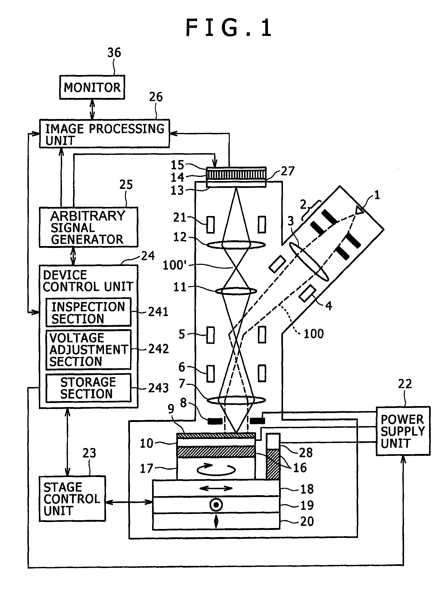
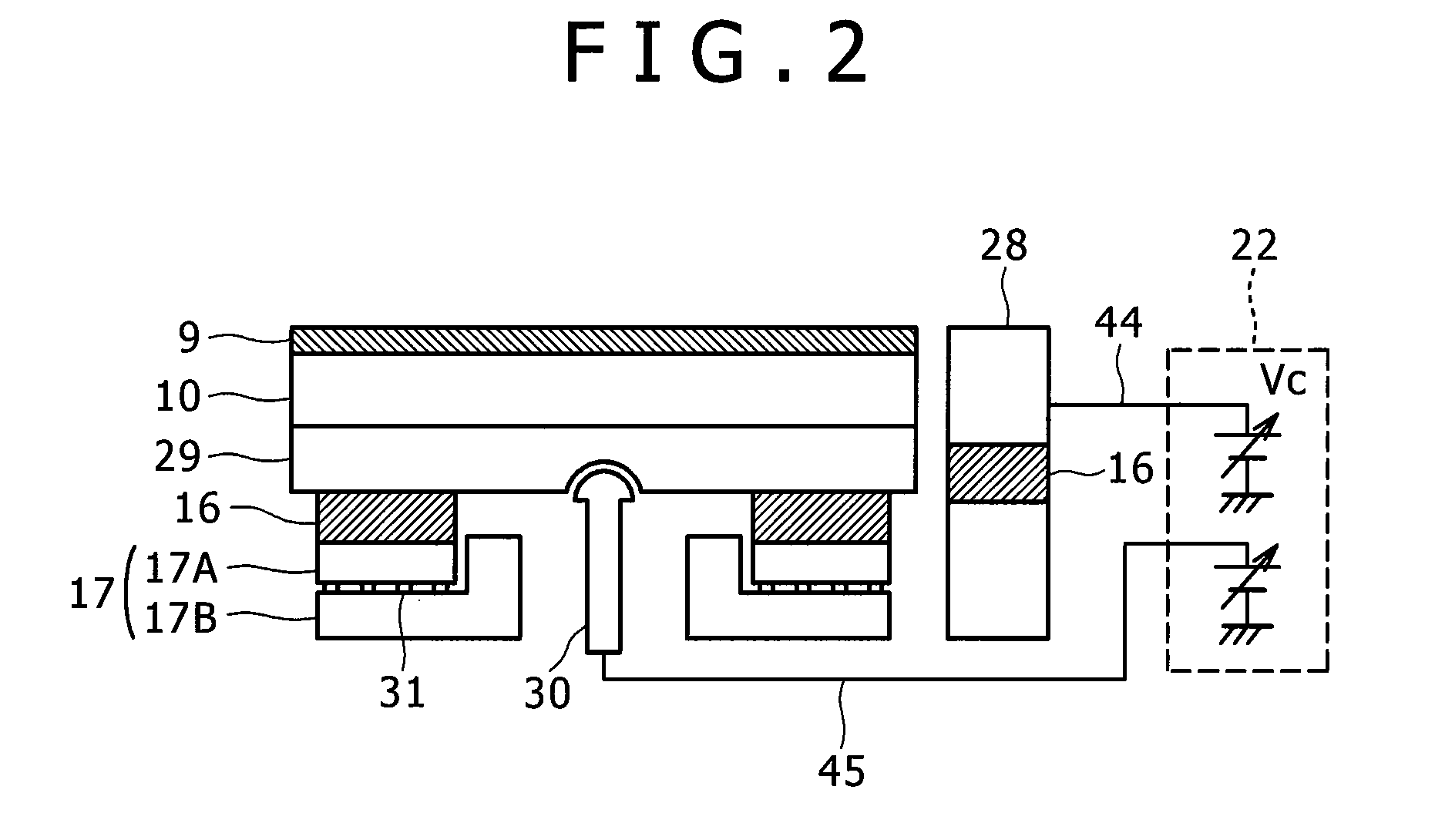
[0039]An inspection device that is according to a first embodiment of the present invention will be explained referring to FIG. 1 to FIG. 10. First, FIG. 1 shows an inspection device according to one embodiment of the present invention, namely an entire configuration of a charged particle beam device. This device roughly consists of an electron beam irradiation optical system, a mirror electron imaging optical system, a stage mechanical system, an electric field control mechanical system, an image detection system, and a control system. However, in this figure, a vacuum pump, its control device, an exhaust pipe, etc. are omitted. The electron beam irradiation optical system includes an electron gun 1, an extraction electrode 2, a condenser lens 3, a deflector 4 means for collimating the beam as main constituents. Although there are cases where various constituents are included in addition to these, their details are omitted. The mirror electron imaging optical system includes a hole...
second embodiment
[0072]Next, another example of performing the observation and inspection of the sample 9 that is performed by the inspection part 241 of the device control unit 24 in the device of the first embodiment will be explained referring to FIG. 11 and FIG. 12.
[0073]First, the operator performs initialization of the inspection conditions by the input operation from the GUI screen of the monitor 36, etc. Step 1101 through Step 1106 of FIG. 11 are the same as Step 901 through Step 906 of FIG. 9 of the first embodiment. The image acquired at Step 1106 is processed in the image processing unit 26, and is subjected to the detection processing to detect the existence / absence of a defect of the sample surface. In this embodiment, the X-stage 18 and the Y-stage 19 are moved little by little from the radius position Ro continuously, for example, to the inside in the radial direction (Step 1107). Next, at Step 1108, it is determined whether the inspection position reaches the termination (R=Re), for ...
third embodiment
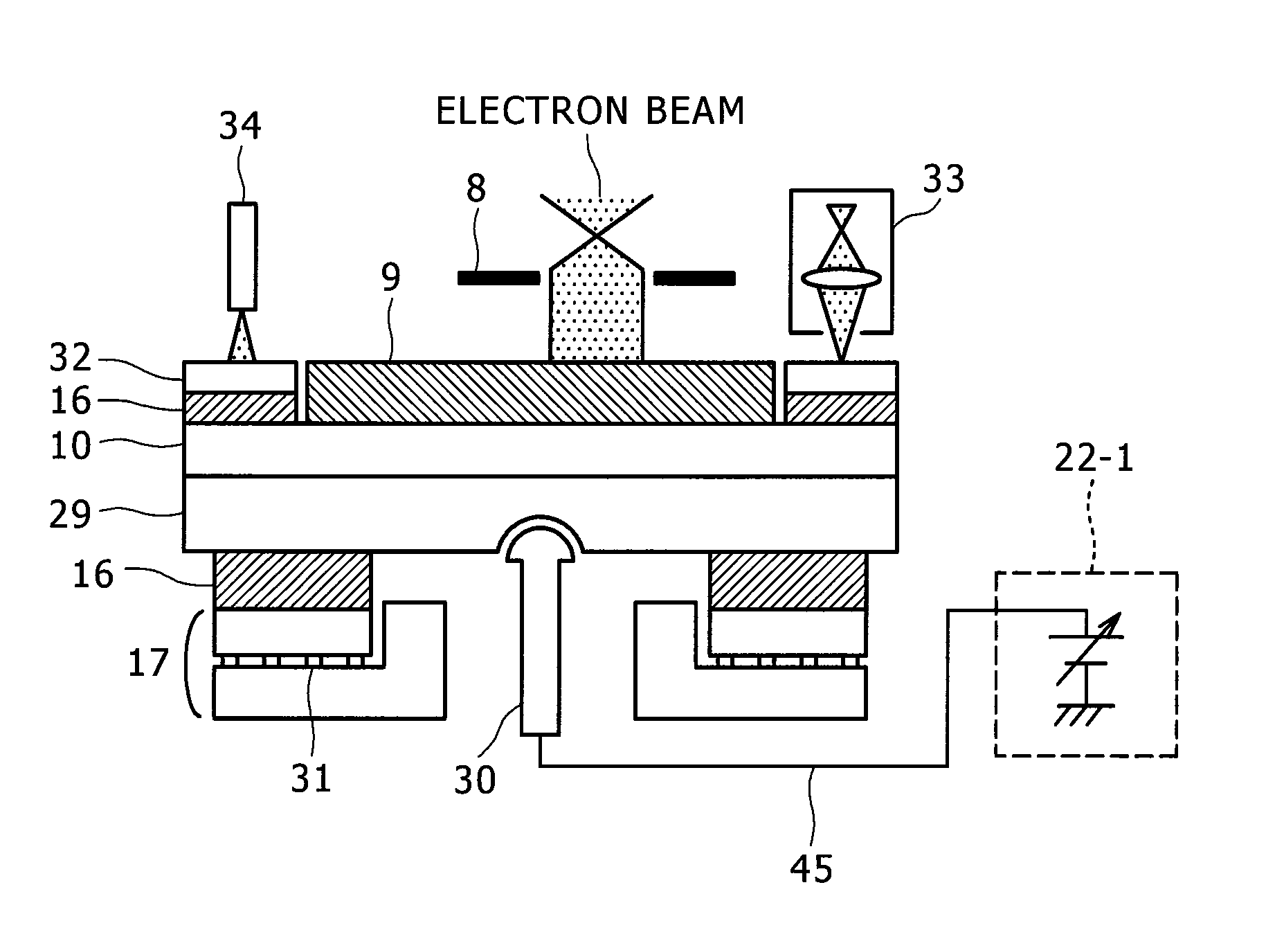
[0076]Next, an inspection device that is according to a third embodiment of the present invention will be explained, referring to FIG. 13 to FIG. 15. First, FIG. 13 is a sectional view of the sample stage and its vicinity of a charged particle beam device according to the third embodiment. It is of the same composition as that of the first embodiment except for the stage mechanical system and the voltage application mechanical system, and the view is drawn omitting the X-stage 18 and some higher-numbered constituents. An electric field control plate 32 isolated by the insulator 16 is provided in the peripheral part of the sample 9 on the sample holder 10. Furthermore, the electric field control electrode 28 is provided on the X-stage 18 in the vicinity of the electric field control plate 32. To the sample 9 and the sample holder 10, the retarding voltage is applied from the power supply unit 22 through the holder receiver 29. To the electric field control electrode 28, a predetermin...
PUM
| Property | Measurement | Unit |
|---|---|---|
| rotation angle | aaaaa | aaaaa |
| length | aaaaa | aaaaa |
| rotation angle | aaaaa | aaaaa |
Abstract
Description
Claims
Application Information
 - R&D
- Intellectual Property
- Life Sciences
- Materials
- Tech Scout
- Unparalleled Data Quality
- Higher Quality Content
- 60% Fewer Hallucinations
Browse by: Latest US Patents, China's latest patents, Technical Efficacy Thesaurus, Application Domain, Technology Topic, Popular Technical Reports.
© 2025 PatSnap. All rights reserved.Legal|Privacy policy|Modern Slavery Act Transparency Statement|Sitemap|About US| Contact US: help@patsnap.com


