System for inspection and imaging of insulated pipes and vessels using backscattered radiation and X-ray fluorescence

a technology of x-ray fluorescence and insulated pipes, which is applied in the field of inspection of insulated pipes and vessels, can solve the problems of affecting the inspection of the pipe itself, requiring a great deal of time and expense, and requiring the removal of the outer insulation for exterior visual inspection not only to save time and expense, but also to avoid corrosion

Inactive Publication Date: 2014-07-01
KING ABDULAZIZ UNIV
View PDF19 Cites 26 Cited by
  • Summary
  • Abstract
  • Description
  • Claims
  • Application Information

AI Technical Summary

Benefits of technology

[0015]These and other features of the present invention will become readil

Problems solved by technology

The insulation layer on the pipes in these plants, as well as in various other industrial applications, is typically at least several centimeters thick, thus making it extremely difficult to inspect the pipe bodies for corrosion.
Plant production must be stopped for interior visual inspection of the pipe walls, and removal of the outer insulation for exterior visual inspection not only requires a great deal of time and expense, but can be detrimental to the pipe itself, since ice forms on the exposed pipe surface for low temperature applications, along with potentially dangerous increases of pressure in the interior, and since heat is lost in high temperature applications.
In addition to visual inspection, other techniques, such as ultrasonic inspection, have been tried, but such methods have typically been found to be difficult to implement due to the inability of the ultrasonic probe to make contact with the pipe or tank wall due to the insulation.
Further, ultrasonic methods typically do not work well in the high temperature environments of fluid-carrying pipes and the like.
Although dire

Method used


Image

  • System for inspection and imaging of insulated pipes and vessels using backscattered radiation and X-ray fluorescence
  • System for inspection and imaging of insulated pipes and vessels using backscattered radiation and X-ray fluorescence
  • System for inspection and imaging of insulated pipes and vessels using backscattered radiation and X-ray fluorescence

Examples


Embodiment Construction

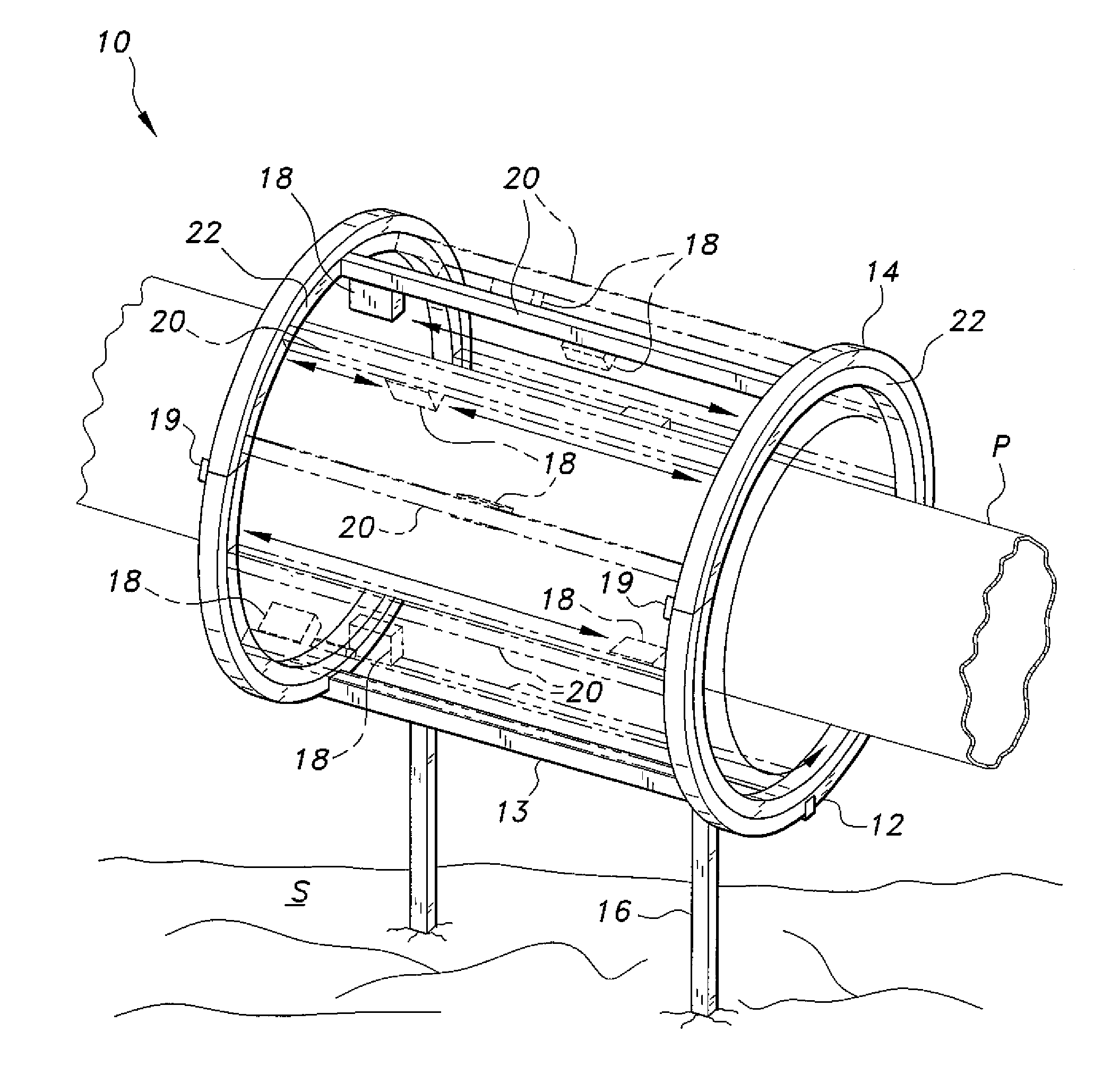
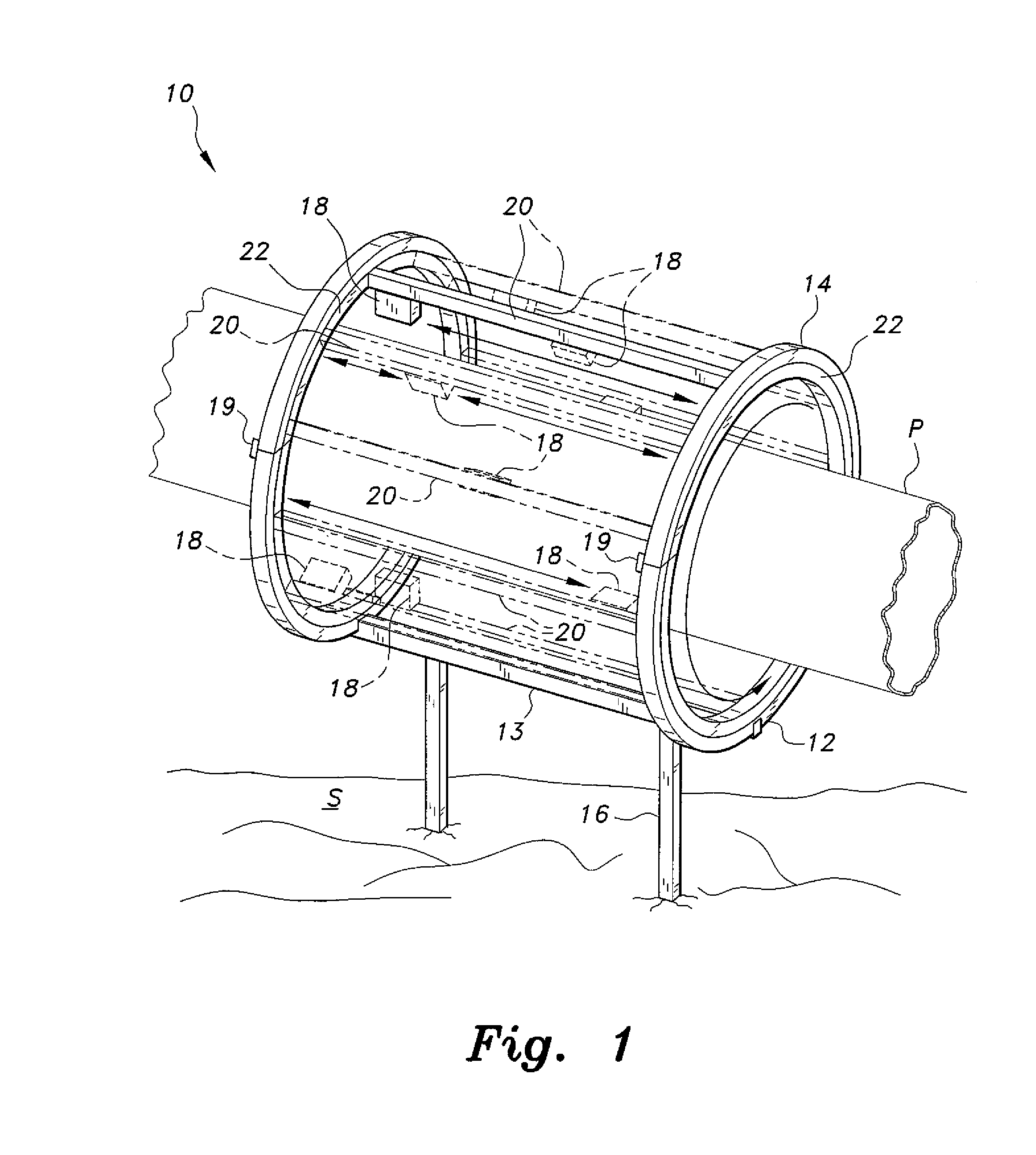
[0028]As shown in FIG. 1, the system for the inspection and imaging of insulated pipes and vessels using backscattered radiation and X-ray fluorescence, designated as system 10 in the drawings, allows for the rapid and accurate inspection and imaging of insulated pipes, vessels and the like using both backscattered gamma radiation and X-ray fluorescence. Although the following description illustrates the system as applied to insulated pipes, it will be understood that the same system may be applied to insulated tanks, heat exchangers, and other insulated objects. The present system allows for multiple inspection modules 18 to be mounted about the periphery of pipe P for simultaneous inspection thereof. In FIG. 1, for exemplary and illustrative purposes, only eight such inspection modules 18 are illustrated. However, it should be understood that any desired number of modules 18 may be used. The plurality of modules 18 preferably encircle the pipe P. It should be further understood th...


PUM


Abstract

The system for the inspection and imaging of insulated pipes and vessels using backscattered gamma radiation and X-ray fluorescence includes a frame having a pair of coaxial rings adapted for coaxial mounting about the insulated pipe, vessel or the like. A pair of rotating supports are rotatably mounted within the pair rings for driven rotation thereof. A plurality of horizontal supports are secured to, and extend between, the pair of rotating supports such that each of the horizontal supports extends along a direction parallel to an axis of the insulated pipe. A plurality of inspection modules are slidably mounted to the horizontal supports. Each inspection module includes at least one radiation source, an X-ray fluorescence detector and a backscattered gamma radiation detector. The plurality of inspection modules are linearly translated along the axial direction of the pipe, and also circumferentially rotated therearound for simultaneous, three-dimensional inspection of the pipe body.

Description

BACKGROUND OF THE INVENTION[0001]1. Field of the Invention[0002]The present invention relates to the inspection of insulated pipes, vessels and the like, and particularly to a system for the inspection of insulated pipes and vessels using backscattered radiation and X-ray fluorescence.[0003]2. Description of the Related Art[0004]Large insulated pipes are often found in numerous industries, such as in gas producing plants for carrying both liquids and gas, particularly for maintaining fluids under low temperatures, in electrical plants for high temperature applications, and in many other industries where both high and low temperature fluids are utilized. The insulation around the pipes is necessary for maintaining relatively low and high fluid temperatures. The insulation layer on the pipes in these plants, as well as in various other industrial applications, is typically at least several centimeters thick, thus making it extremely difficult to inspect the pipe bodies for corrosion. ...

Claims


Application Information

Patent Timeline
IPC IPC(8): G01B15/08G01N23/203G01V5/12H05G1/02
CPCH05G1/02G01N23/223G01V5/12G01N23/203G01N23/2206G01B15/02G01N2223/076
Inventor ALZAIDI, SAMIR, ABDUL-MAJID
Owner KING ABDULAZIZ UNIV
Why Eureka
Try Eureka