
Heating and cooling apparatus

a technology for heating apparatus and fans, which is applied in lighting and heating apparatus, ventilation systems, heating types, etc., can solve the problems of adding cost, complexity, and additional failure opportunities, and achieves the effect of reducing the airflow rate and high airflow ra

Active Publication Date: 2014-07-01
SEVILLE CLASSICS INC +1
View PDF9 Cites 6 Cited by
  • Summary
  • Abstract
  • Description
  • Claims
  • Application Information

AI Technical Summary

Benefits of technology

The present invention is a portable air blowing appliance that can be used to cool down the user or warm the surrounding environment. It has a scroll that helps direct the airflow and a blower that can be adjusted to control the airflow rate. The technical effect of this invention is to provide a convenient and efficient way to cool or warm up the user's surroundings in a portable appliance form.

Problems solved by technology

Variable air flow rates from centrifugal blowers are typically achieved by variation of the motor speed, either by using a speed controller or by including a multitude of taps into the motor coil, either of which adds cost, complexity, and an additional opportunity for failure compared to a single speed blower.

Method used


Image

  • Heating and cooling apparatus
  • Heating and cooling apparatus
  • Heating and cooling apparatus

Examples


Embodiment Construction

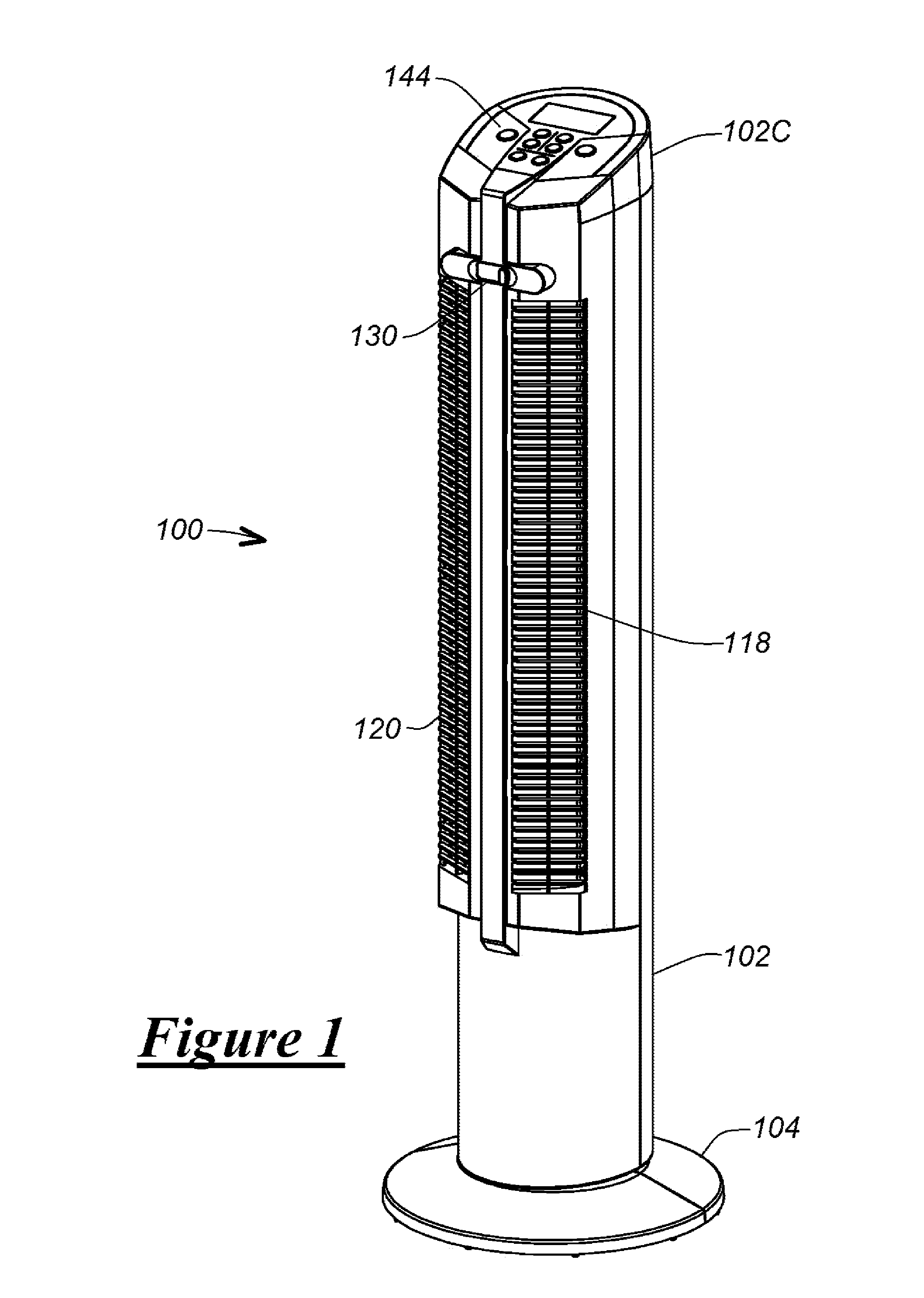
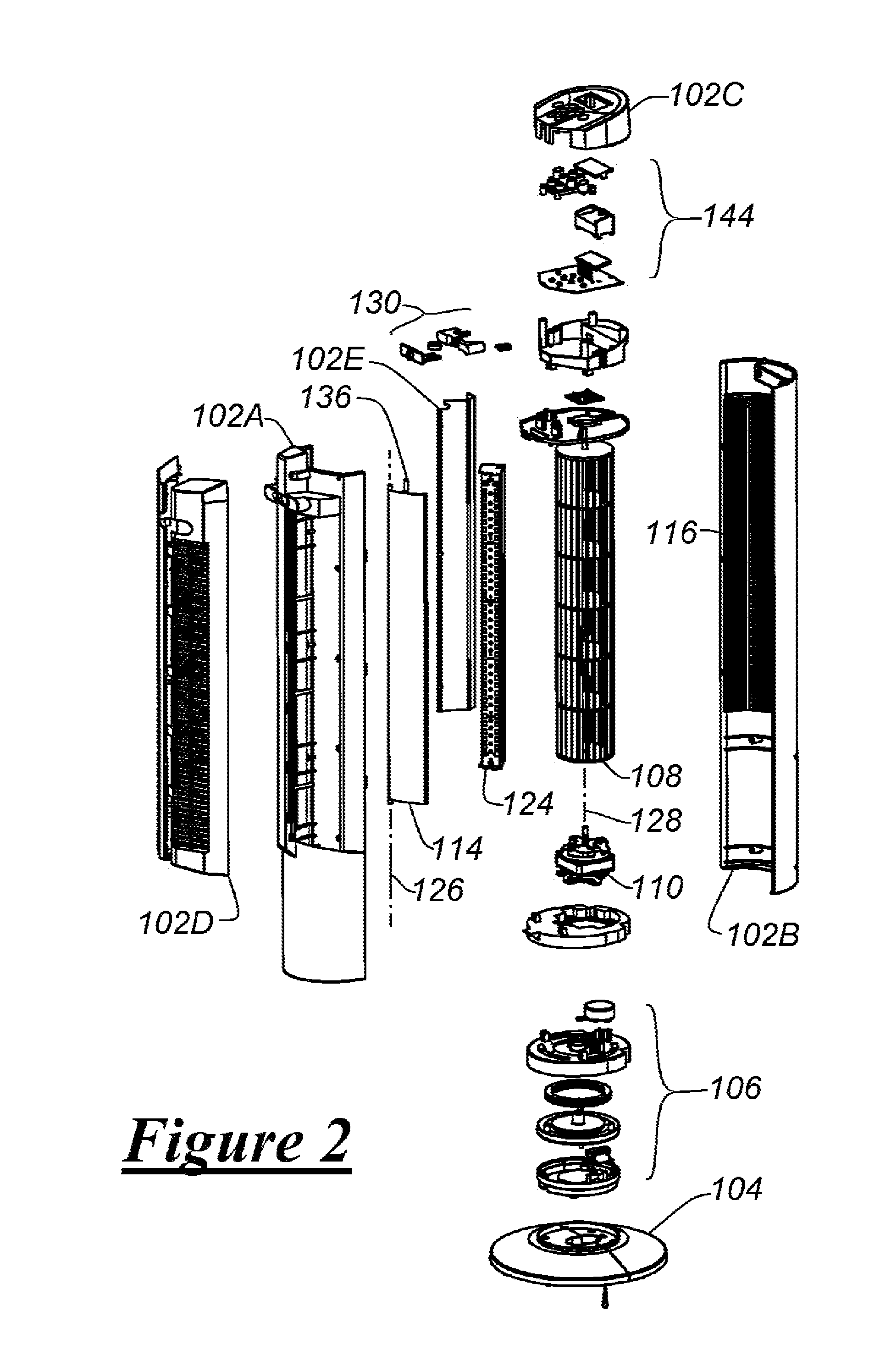
[0034]FIGS. 1-15 illustrate a portable air blowing appliance 100 according an exemplary embodiment of the present invention. The appliance includes a housing 102 and a base 104, connected by a motorized oscillation arrangement 106. The housing is made of front cover 102A, rear cover 102B, top cover 102C, front grill 102D, and cut-off 102E.

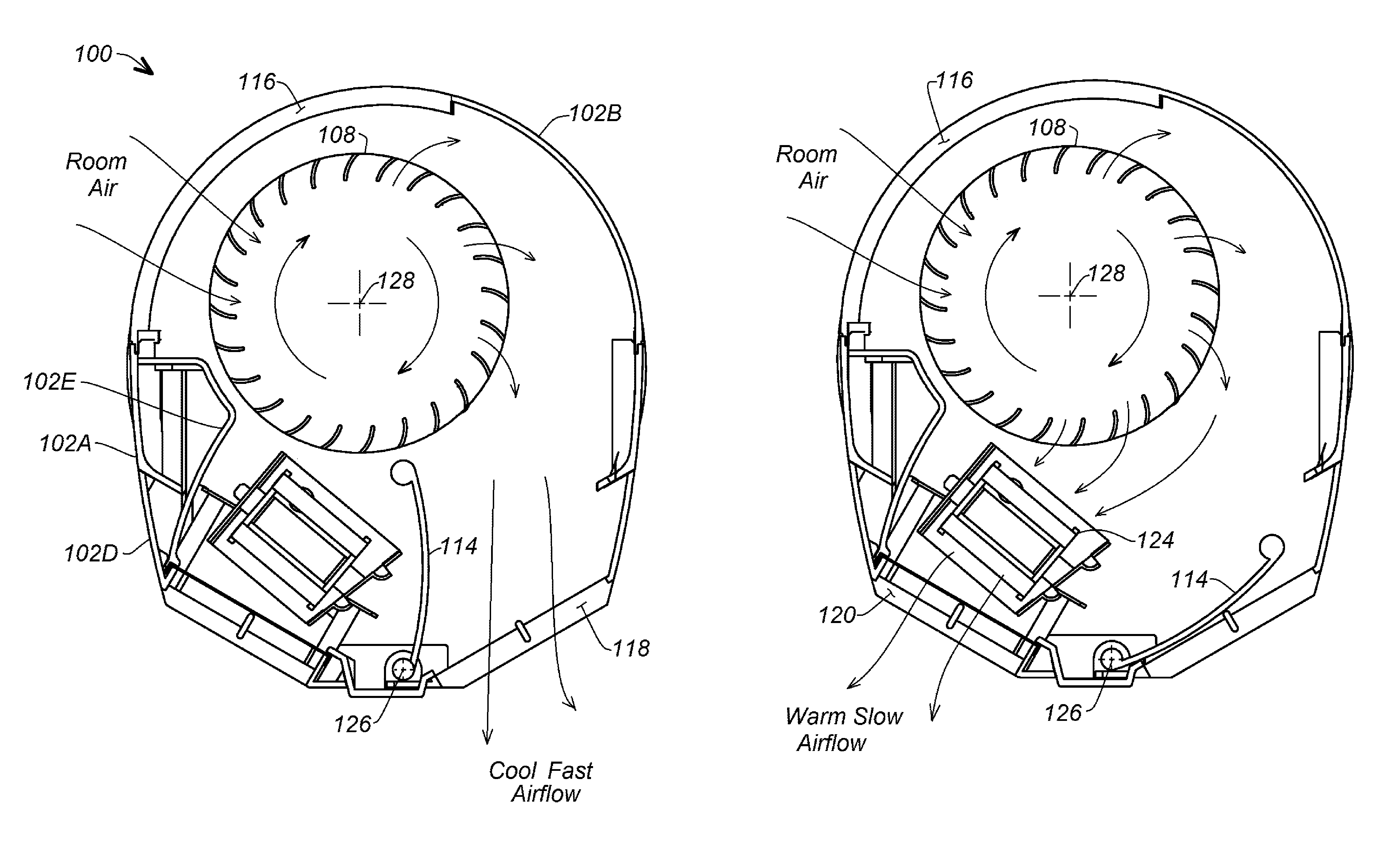
[0035]The elongate front and rear covers, together with the cut-off, are assembled around, and form a scroll around blower wheel 108, which is connected to and rotatable by electric blower motor 110. Deflector 114, movable within the housing, serves as a changeable air director in conjunction with the scroll.

[0036]As seen best in FIGS. 14 and 15, clockwise rotation of the blower wheel within the scroll formed by the surrounding housing causes air to be sucked into the wheel through intake grill 116 and to be forced centrifugally from the wheel to be directed by the scroll and deflector and blown forwardly from the appliance through the front grill....


PUM


Abstract

A portable air blowing appliance has a housing retaining a blower adapted when energized to create an airflow through and from the housing, and a heating element adapted when energized to impart heat to the airflow. A movable deflector selectively steers the airflow either though or not through the heating element. In the exemplary embodiment shown, the blower is, in combination, a motor-driven centrifugal blower rotatable about a blower axis to create the airflow, and a scroll surrounding the blower wheel and adapted to direct the airflow from the blower wheel forwardly from the housing. In this exemplary embodiment, the deflector is movable about a pivot axis perpendicular to the blower axis between a heating position wherein the airflow is steered through the heating element and a cooling position where the airflow is steered not through the heating element.

Description

FIELD OF THE INVENTION[0001]This invention relates to household heaters, fans and blowers, and more specifically, to such portable appliances having centrifugal blower wheels surrounded by scrolls for directing a warm or cool airflow into the surrounding environment.BACKGROUND OF THE INVENTION[0002]There is an ever-increasing need to obtain localized heating at home and in the work place. There is also an ever-increasing need to obtain localized cooling or ventilating air flow in those places. As costs rise and incomes fall in a declining economy, the need to obtain a variety of such functions in a single portable appliance becomes more and more advantageous.[0003]Existing air blowing appliances typically prevail in two main types; axial fans and centrifugal blowers. Axial fans have an electric motor typically oriented such that its rotational axis is aligned with the direction of air movement. An air propeller affixed to the motor's rotor rotates about the axis and causes air to be...

Claims


Application Information

Patent Timeline
Patent Type & Authority Patents(United States)
IPC IPC(8): F24D15/02F24H3/02
CPCF24F2001/004F24H9/0057F24H3/0417F24F1/005
Inventor TAI, YUNG-MINGHO, EDWIN
Owner SEVILLE CLASSICS INC
Learn More