Regional clock gating and dithering

a clock signal and region clock technology, applied in the direction of generating/distributing signals, pulse techniques, instruments, etc., can solve the problems of reducing the effective frequency the duty cycle of the operational clock signal, so as to save power and the effect of effective frequency of the clock signal

Active Publication Date: 2014-07-01
APPLE INC
View PDF13 Cites 11 Cited by
  • Summary
  • Abstract
  • Description
  • Claims
  • Application Information

AI Technical Summary

Benefits of technology

[0007]In one embodiment, the first idle state may be a state in which further forward progress of IC operation is not being made, but is expected to be made in the future due to some externality. One such example would be a level two (L2) cache miss in a processor. If a cache miss occurs, forward progress of the processor may be halted during the latency period in which data is accessed from the memory of the system in which the processor is implemented. Since this latency may be large relative to the processing speed, the idle time waiting for data to return from the memory may be used to save power, although it may nevertheless be desirable to keep the processor in an active state. Accordingly, instead of clock-gating the processor or functional units therein, the control unit may cause the duty cycle and effective frequency of the clock signal to be reduced. This may save power in the clock tree while allowing the various logic circuits of the processor to otherwise remain active.

Problems solved by technology

The control unit may cause the root clock-gating circuit to dither the clock signal if the functional units of the IC are idle or expected to be idle, wherein dithering includes reducing the duty cycle of the operational clock signal and thus reducing its effective frequency.

Method used


Image

  • Regional clock gating and dithering
  • Regional clock gating and dithering
  • Regional clock gating and dithering

Examples


Embodiment Construction

Integrated Circuit

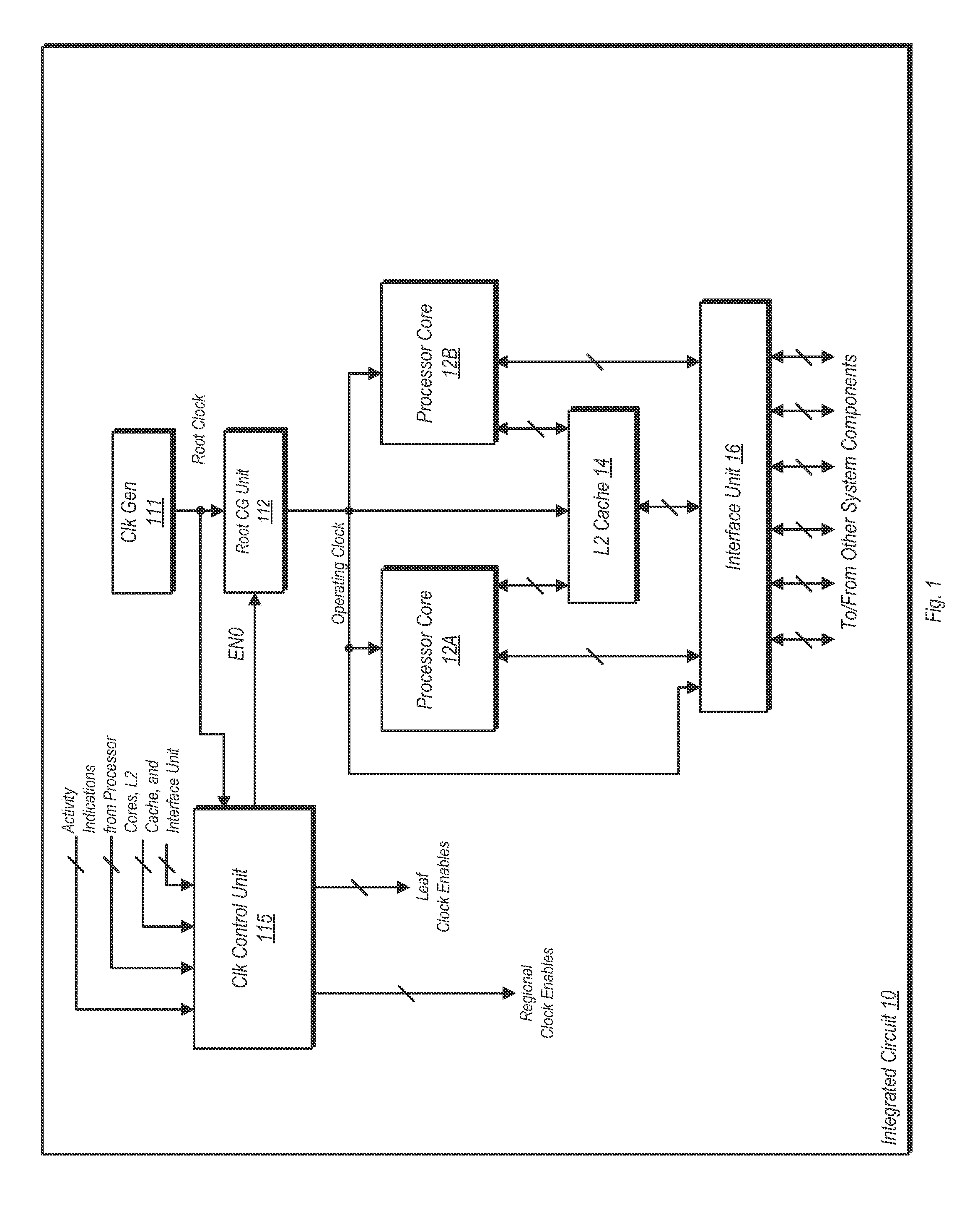
[0018]Turning now to FIG. 1, a block diagram of one embodiment of an integrated circuit (IC) is shown. In the embodiment shown, IC 10 is a system-on-a-chip (SOC) that includes multiple processor cores and other circuitry. It is noted that not all components of the SOC are shown here, as other functional blocks may be present. Additionally, it is noted that the discussion with respect to an SOC presented here is for the sake of example. Accordingly, other embodiments of an IC are possible and contemplated for use with the various method and apparatus embodiments disclosed herein.

[0019]In the embodiment shown, IC 10 includes processor cores 12A and 12B, a level two (L2) cache 14, and an interface unit 16. The interface unit 16 may provide an interface to a bus on the IC 10, and may additionally provide interfaces to other components, some of which may be on-chip while other such components may be off-chip. Such components may include (but are not limited to) memories...


PUM


Abstract

A system and method for dithering a clock signal during idle times is disclosed. An integrated circuit (IC) includes a number of functional units and a clock tree. The clock tree includes a root level clock-gating circuit, a number of regional clock-gating circuits, and a number of leaf level clock-gating circuits. The root level clock-gating circuit is coupled to distribute an operating clock signal to the regional clock-gating circuits, while the regional clock-gating circuits are each configured to distribute the operating clock signal to correspondingly coupled ones of the leaf level clock-gating circuits. The IC may further include a control unit configured to monitor activity levels and indications from each of the functional units. The control unit may cause the root clock-gating circuit to dither the clock signal if the IC is idle, wherein dithering includes reducing the duty cycle and the effective frequency of the operating clock signal.

Description

BACKGROUND[0001]1. Technical Field[0002]This disclosure relates to integrated circuits, and more particularly, to the control of a clock signal to circuitry implemented on an integrated circuit.[0003]2. Description of the Related Art[0004]Clock-gating is a power saving technique that is employed in a wide variety of integrated circuits (ICs). In an IC operable to perform clock-gating, extra hardware in the form of clock-gating logic is added to various points of a clock tree that is used to distribute a clock signal. A point of a clock tree used to distribute the clock signal directly to circuitry (e.g., flop circuits) may be referred to as a “leaf” node. Accordingly, clock-gating logic may be placed at the leaf node. The clock-gating logic of each leaf node may be coupled to receive an enable signal that, when asserted, enables the clock signal to be provided to the clock circuitry associated with that leaf node. The enable signal may be de-asserted to inhibit the clock signal from...

Claims


Application Information

Patent Timeline
Patent Type & Authority Patents(United States)
IPC IPC(8): G06F1/00H03K19/00
CPCY02B60/1221G06F1/3237G06F1/10H03K19/0016Y02D10/00
Inventor ZIESLER, CONRAD H.MYLIUS, JOHN H.KASSOFF, JASON M.
Owner APPLE INC
Why Eureka
Try Eureka