Flash suppressing and recoil compensating muzzle device

a recoil compensating and flash suppressing technology, applied in the field of muzzle devices, can solve the problems of undesirable side effects, light emission and recoil, adversely affecting the speed and accuracy of subsequent discharges of firearms,

Active Publication Date: 2014-07-08
COLEMAN WILLIAM JAMES
View PDF13 Cites 8 Cited by
  • Summary
  • Abstract
  • Description
  • Claims
  • Application Information

AI Technical Summary

Problems solved by technology

Light emission and recoil are two undesirable side effects commonly experienced upon discharging a firearm.
Both side effects can adversely affect the speed and accuracy of subsequent discharges from a firearm.
The backwards momentum felt by a shooter can directly impeded the ability of a shooter to maintain proper alignment with a target and cost valuable time in order to readjust alignment.
While a variety of muzzle attachments have been developed in order to mitigate or eliminate muzzle flash and recoil, many of the devices fall short of addressing both side effects effectively.
Unfortunately one disadvantage experienced with some of these recoil mitigating devices is potentiating ignition of the propellant gases.
On the other hand, some muzzle devices intended to reduce muzzle flash fail to manage recoil.
Unfortunately, to reduce muzzle flash, the propellant gases are generally dispersed in a manner resulting in no significant compensation to recoil or muzzle climb.
While it has long been understood that recoil can be reduced by redirecting propellant gases to the side and the rear of a weapon, historically, these attempts not been able to mitigate muzzle flash intensity.
Although there have been several designs that have sought to overcome this disadvantage, few designs have achieved significant success.
As a result of this situation, many muzzle devices have abandoned recoil management in favor of flash suppression.
Currently open ended style muzzle devices, such as those by of Advanced Armament Corp., LLC (Brittingham U.S. Pat. No. 7,905,170), BE Meyers (Meyers U.S. Pat. No. 6,837,139 and Meyers U.S. Pat. No. 7,302,774) and Smith Enterprises (Sommers U.S. Pat. No. 5,596,161) all effectively suppress flash, but lack effective recoil management.
Such open end muzzle devices also have a tendency to ring loudly after firing, as a result of harmonic resonance between the prongs positioned radially around the bore line.
This lingering sound is an undesired side effect of current flash suppressing muzzle devices.
This distinct sound signature produced by current flash suppressing muzzle devices is at best a subtle annoyance and at worst an audible indicator for locating the position of the firearm operator.
Furthermore, the asymmetric placement of the narrowing exhaust openings allows the prongs to be of variable size which reduce the production of audible harmonic resonant ringing.

Method used


Image

  • Flash suppressing and recoil compensating muzzle device
  • Flash suppressing and recoil compensating muzzle device
  • Flash suppressing and recoil compensating muzzle device

Examples


Embodiment Construction

[0014]All illustrations of the drawings are for the purpose of describing selected versions of the present invention and are not intended to limit the scope of the present invention.

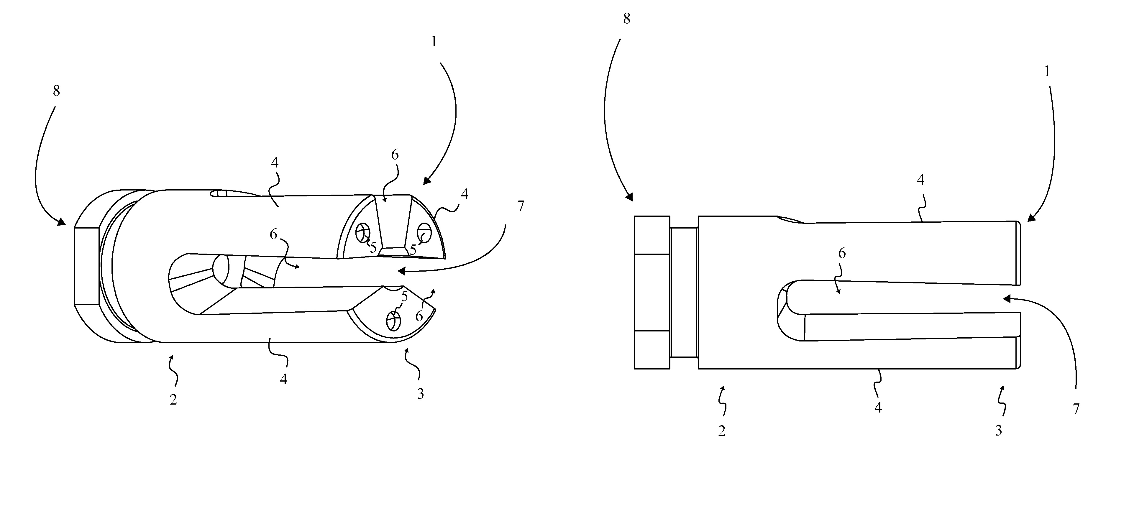
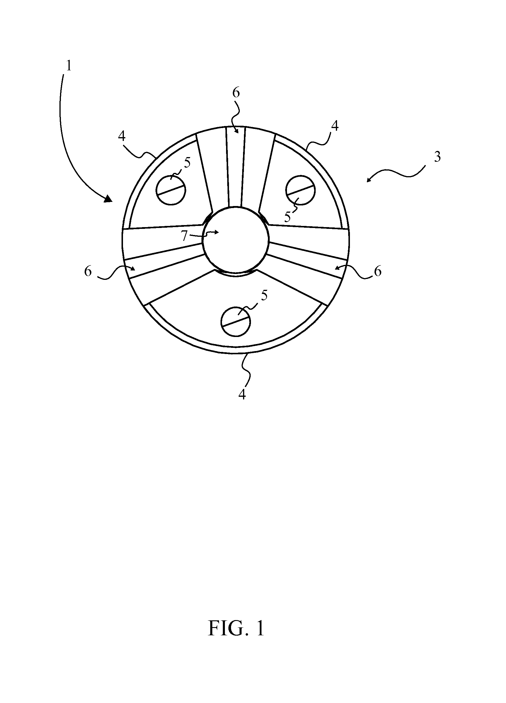
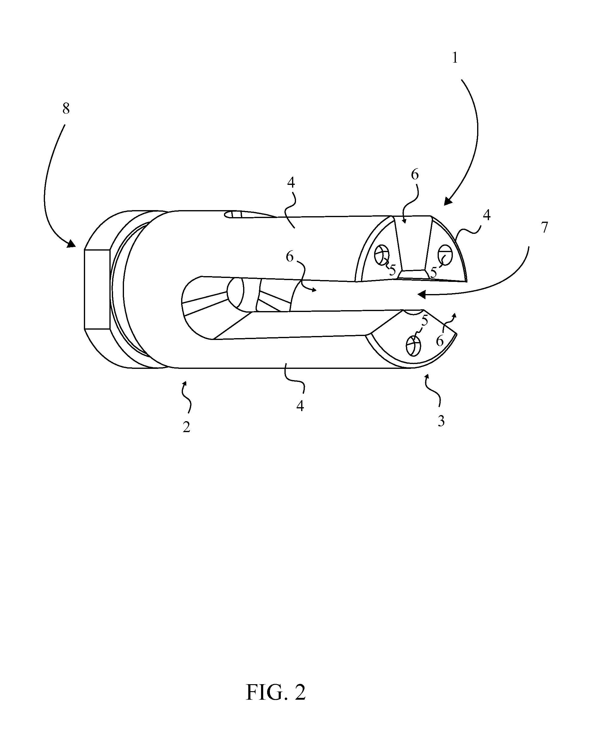
[0015]Referencing FIG. 1 and FIG. 2, the present invention is a combination muzzle device that is found at the terminal end of a firearm's barrel in order to mitigate recoil and reduce muzzle flash after discharging the firearm. The present invention accomplishes this while preventing audible ringing due to harmonic resonance. The combination muzzle device comprises a cylindrical open ended structure 1, a bore 7, and a terminal end mount 8. The cylindrical open ended structure 1 allows the escape of propellant gases in a fan pattern that substantially decreases light emissions and dampens recoil upon discharge of the firearm. The terminal end mount 8 is coupled to the terminal end of a firearm's barrel. The terminal end mount 8 is found positioned concentrically with the cylindrical open ended structure ...


PUM


Abstract

A flash suppressing and recoil compensating muzzle device for use with a firearm provides a muzzle device that reduces recoil and inhibits muzzle flash while preventing audible harmonic resonant ringing after the firearm is discharged. The present invention accomplishes this through the use of an open ended muzzle device that redirects a portion of the high velocity gasses exiting the terminal end of the weapon through asymmetrically placed narrowing exhaust openings. The asymmetrically placed narrowing exhaust openings gradually direct exiting gases to the rear and to the sides of the muzzle in order to reduce recoil and reducing light emissions. The narrowing exhaust openings are formed by the radially positioned prongs of a distinct weight and width, which widen from the proximal to distal end of the muzzle device. The weight and mass disparity between prongs prevents audible ringing by reducing resonant vibrations between neighboring prongs.

Description

FIELD OF THE INVENTION[0001]The present invention relates generally to a muzzle device, more specifically to a flash suppressing and recoil compensating muzzle device for use with firearms, which through the arrangement of a plurality of prongs is able to effectively divert propellant gases in a manner that reduces muzzle flash and recoil upon discharging the weapon.BACKGROUND OF THE INVENTION[0002]Light emission and recoil are two undesirable side effects commonly experienced upon discharging a firearm. Both side effects can adversely affect the speed and accuracy of subsequent discharges from a firearm. Recoil is the backwards momentum felt by a shooter as a result of the forward momentum of the projectile and the expanding gases exiting the barrel. The backwards momentum felt by a shooter can directly impeded the ability of a shooter to maintain proper alignment with a target and cost valuable time in order to readjust alignment. Light emission produced upon discharging a firearm...

Claims


Application Information

Patent Timeline
Patent Type & Authority Patents(United States)
IPC IPC(8): F41A21/00
CPCF41A21/36F41A21/34
Inventor COLEMAN, WILLIAM, JAMES
Owner COLEMAN WILLIAM JAMES
Why Eureka
Try Eureka