Structural infill wall panel module

a technology of wall panels and structural components, applied in the direction of walls, building roofs, parkings, etc., can solve the problems of high manufacturing cost of metal subframes and time-consuming installation of systems, and achieve the effect of improving strength

Active Publication Date: 2014-07-08
KINGSPAN HLDG (IRL) LTD
View PDF18 Cites 9 Cited by
  • Summary
  • Abstract
  • Description
  • Claims
  • Application Information

AI Technical Summary

Benefits of technology

[0019]In one embodiment a support member extends longitudinally between the brackets. Panel fixings may extend through the panel and into the longitudinal support member for enhanced strength.

Problems solved by technology

However, such metal sub-frames are expensive to manufacture and the systems are time consuming to install.
On site detailing errors and poor workmanship on installation can also lead to problems.

Method used


Image

  • Structural infill wall panel module
  • Structural infill wall panel module
  • Structural infill wall panel module

Examples


Embodiment Construction

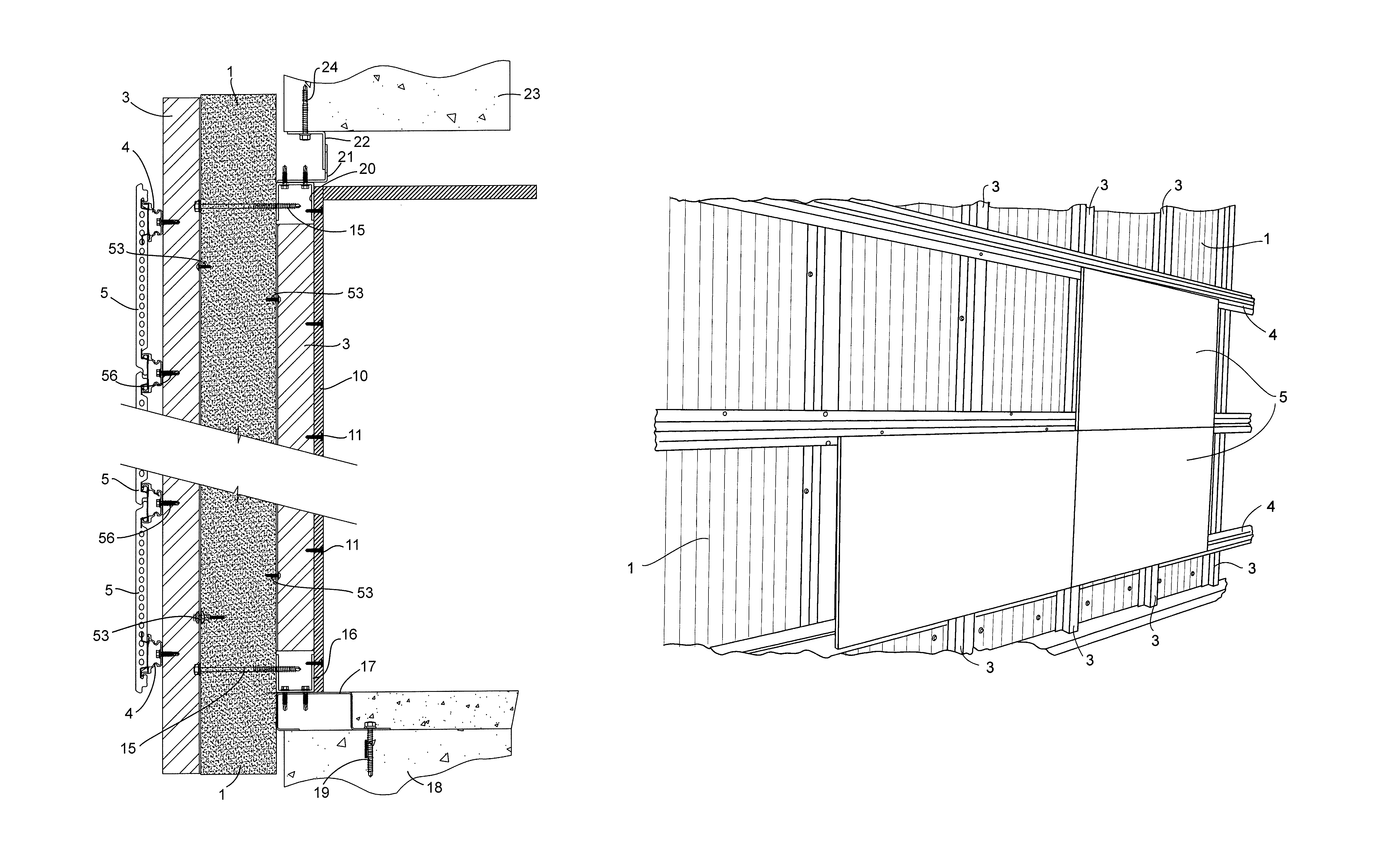
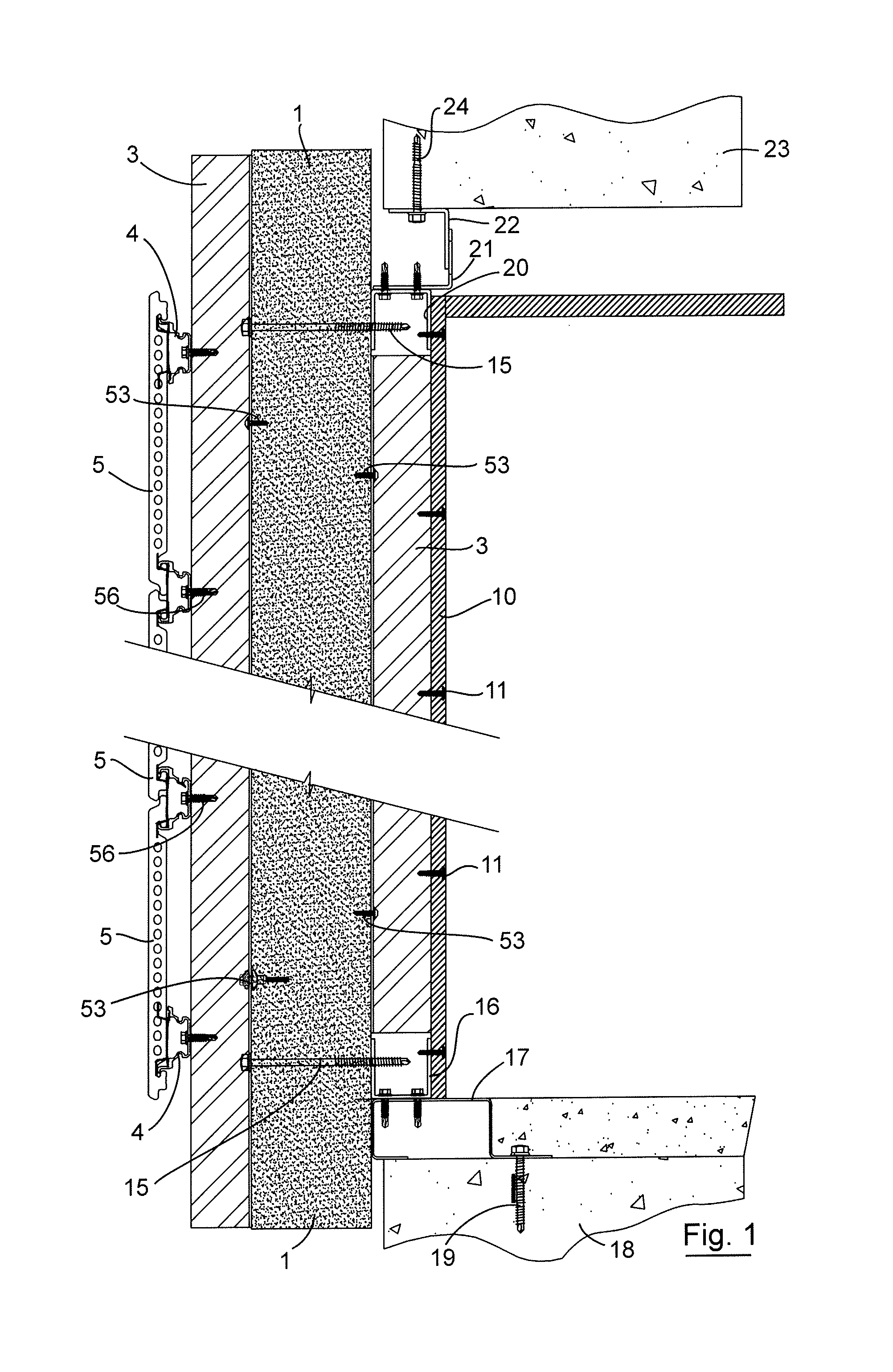
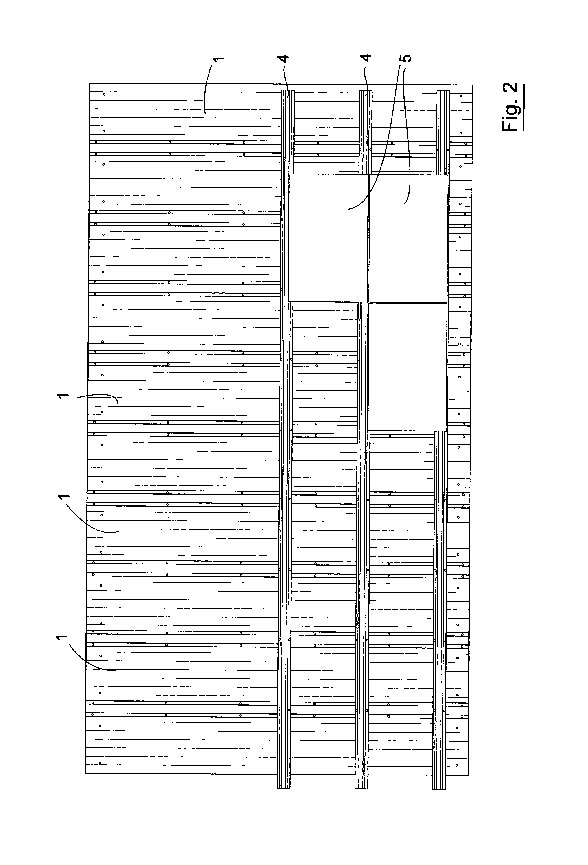
[0091]Referring to the drawings there is illustrated a wall façade system according to the invention. The system comprises a structural infill modular panel system that is installed into a building mainframe without a requirement for a secondary framing system.

[0092]The wall panel module of the invention comprises a plurality of insulating panels 1 which have connection means on opposite sides thereof for interengaging the panels 1 together at joints 2 (see for example FIG. 6) between the panels 1. Reinforcing bridging elements in the form of top hat sections 3 bridge the joints 2 between adjacent panels 1. On the front or external face of the system support elements 4 are mounted to the reinforcing top hat sections 3 and external cladding elements 5 are mounted to the support elements 4.

[0093]Additional reinforcing elements in the form of top hat sections 3 are in this case provided mid-way across the width of the panel. For example, if the panels are typically 1200 mm wide the rei...


PUM


Abstract

A facade / wall system comprises a number of modules. Each module comprises a plurality of insulating panels which have connection means on opposite sides thereof for interengaging the panels together at joints between the panels. Reinforcing elements in the form of top hat sections bridge the joints between adjacent panels. The top hat reinforcement elements used to interconnect adjacent panels in a module ensure that the composite panels act together as monolithic structure that creates a diaphragm while providing a surface to which cladding can be fixed and also providing a cavity between the panels and the cladding attached to the modules. They stiffen the panels and thereby enhance resistance to deflection. The system is cost effective and relatively easy and quick to install.

Description

[0001]This is a national stage of PCT / IE11 / 000,030 filed Jun. 8, 2011 published in English, which has a priority of Irish no. 2010 / 0367 filed Jun. 8, 2010, and Irish no. 2011 / 0058 filed Feb. 9, 2011, hereby incorporated by reference.INTRODUCTION[0002]Many multi-storey buildings are constructed by first installing a main building frame that defines the various floors of the building. Subsequently external walls are installed between the elements of the main frame. In general, such external walls comprise a metal sub-frame to which various infills and cladding are fitted. However, such metal sub-frames are expensive to manufacture and the systems are time consuming to install. On site detailing errors and poor workmanship on installation can also lead to problems.[0003]There is therefore a need for a wall system which will provide the necessary mechanical and other characteristics but which will be less expensive and less prone to on-site errors than metal sub-frame systems.STATEMENTS...

Claims


Application Information

Patent Timeline
Patent Type & Authority Patents(United States)
IPC IPC(8): E04B2/52E04B2/08E04C1/40
CPCE04B2/08E04B2/90E04F13/0803E04F13/0819E04F13/0876E06B1/04E04B1/6112E04B1/612E04F13/081
Inventor CAROLAN, JAMESFLYNN, GREGORY
Owner KINGSPAN HLDG (IRL) LTD
Why Eureka
Try Eureka