Physical quantity sensor

a technology of physical quantity and sensor, applied in the direction of fluid pressure measurement, acceleration measurement using interia force, instruments, etc., can solve the problems of reducing the accuracy of vibration frequency, unable to accurately measure a strain or load acting on the movable end, etc., to achieve higher output voltage, reliably generate the fundamental vibration mode, and the effect of higher output voltag

Inactive Publication Date: 2014-07-08
PANASONIC CORP
View PDF27 Cites 0 Cited by
  • Summary
  • Abstract
  • Description
  • Claims
  • Application Information

AI Technical Summary

Benefits of technology

[0015]A physical quantity sensor of the present invention includes a beam-like vibrating body and a fixing part that supports both ends of this vibrating body. A first piezoelectric element is formed on a central portion of the vibrating body, and a second piezoelectric element and third piezoelectric element are formed on both ends of the vibrating body. The first piezoelectric element acts as a driving element, and the second piezoelectric element and the third piezoelectric element act as feedback elements, so as to cause the beam-like vibrating body to generate natural vibration. A physical quantity acting on the beam-like vibrating body is detected by measuring a natural frequency of the vibrating body. This configuration enables the generation of a fundamental vibration mode in which vibration displacement is distributed symmetrically to the center of the beam-like vibrating body. Accordingly, the present invention offers an effect that a physical quantity, such as a strain or load, acting on an object can be reliably detected.
[0016]Another physical quantity sensor of the present invention includes a beam-like vibrating body, and a fixing part supporting both ends of this vibrating body. A first piezoelectric element is formed on the central portion of the vibrating body. A second piezoelectric element and a third piezoelectric element are formed on both ends of the beam-like vibrating body. The first piezoelectric element formed on the central portion of the beam-like vibrating body acts as a feedback element, and second and third piezoelectric elements formed on both ends of the beam-like vibrating body act as driving elements. The second piezoelectric element and the third piezoelectric element are configured to be driven with the same amplitude in the same phase. This configuration enables generation of the fundamental vibration mode in which vibration displacement is distributed symmetrically to the center of the beam-like vibrating body. In addition, the feedback element is disposed at a position where the vibration amplitude is the highest, that is, in the center of the beam-like vibrating body. A higher output voltage can thus be obtained from the feedback element. Accordingly, the present invention offers an effect that a physical quantity, such as a strain or load, acting on an object can be reliably detected.
[0017]Still another physical quantity sensor of the present invention includes a beam-like vibrating body and a fixing part supporting both ends of this vibrating body. A first piezoelectric element is formed on a central portion of the vibrating body. A second piezoelectric element and a third piezoelectric element are formed on both ends of the vibrating body. The first piezoelectric element formed on the central portion of the vibrating body acts as a detecting element. The second and the third piezoelectric elements formed on both ends of the beam-like vibrating body act as driving elements. The fourth and fifth piezoelectric elements are further formed near the second and third piezoelectric elements as feedback elements. The vibrating body generates natural vibration by driving the second piezoelectric element and the third piezoelectric element with the same amplitude in the same phase. The feedback elements measure a natural frequency of the beam-like vibrating body. This configuration reliably generates the fundamental vibration mode, in which vibration displacement is distributed symmetrically to the center of the beam-like vibrating body, by detecting the vibration state of the beam-like vibrating body near the driving element using the feedback elements. In addition, since the detecting element is disposed at a position where the vibration amplitude is the highest, that is, in the center of the beam-like vibrating body, a higher output voltage can thus be obtained from the detecting element. Accordingly, the present invention offers an effect that a physical quantity, such as a strain or load, acting on an object can be further reliably detected.

Problems solved by technology

In some cases, this causes a failure to accurately measure a strain or load F acting on movable end 5 of flexure element 1.
This reduces amplitude in feedback element 105, thus reducing the accuracy of vibration frequency.

Method used


Image

  • Physical quantity sensor
  • Physical quantity sensor
  • Physical quantity sensor

Examples


first exemplary embodiment

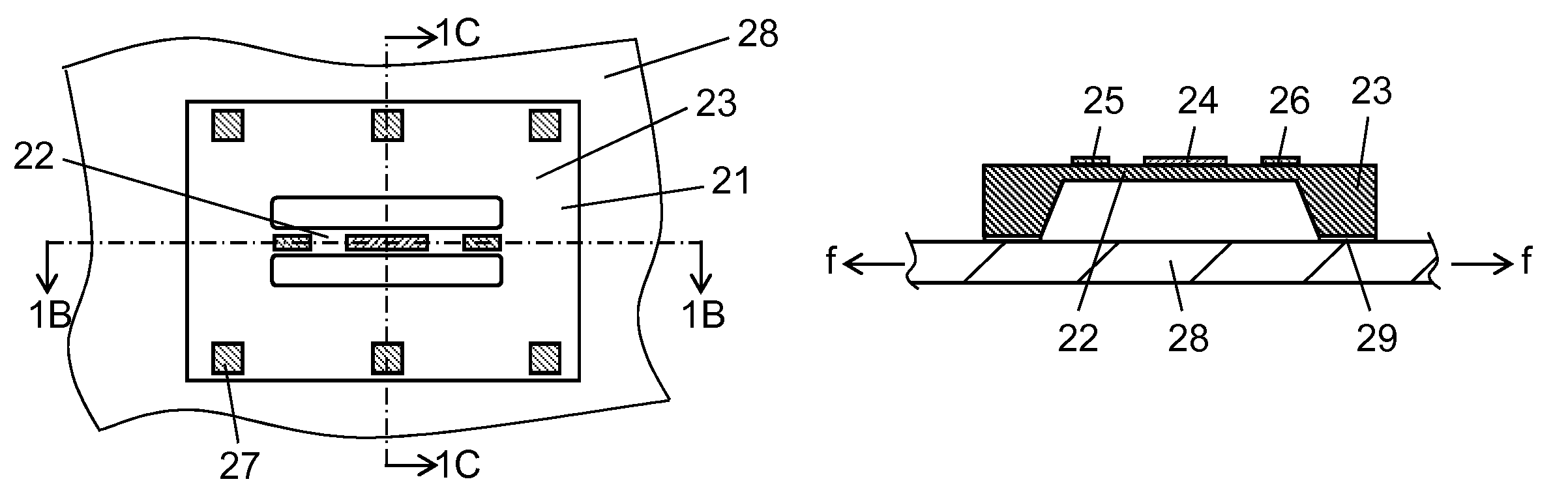
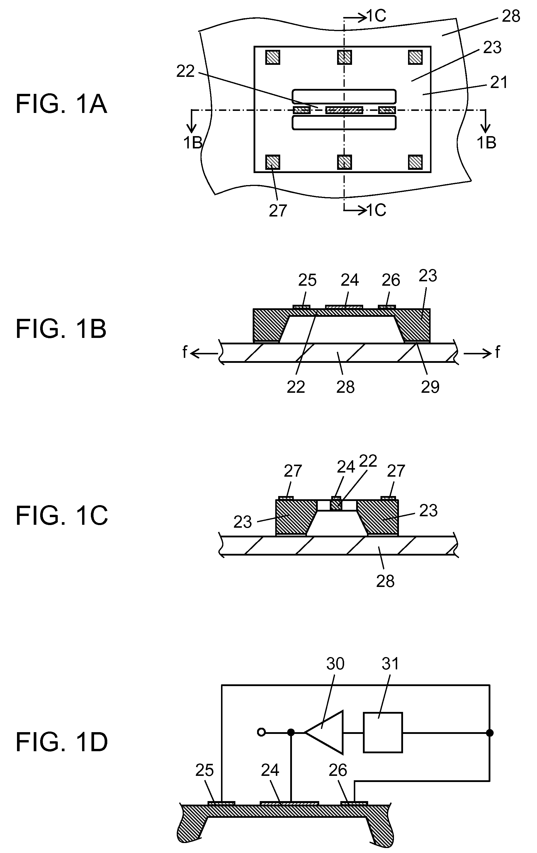
[0036]FIG. 1A is a top view of a physical quantity sensor in the first exemplary embodiment of the present invention. FIG. 1B is a sectional view taken along line 1B-1B in FIG. 1A. FIG. 1C is a sectional view taken along line 1C-1C in FIG. 1A. FIG. 1D illustrates an amplifier and a gain adjustment and phase shifting unit connected to the physical quantity sensor in FIG. 1B. In FIGS. 1A to 1D, semiconductor substrate 21 is typically made of silicon, and an insulating layer (not illustrated) of an oxide silicon layer or a silicon nitride layer is formed on its surface. Beam 22 is formed by etching semiconductor substrate 21. Beam 22 configures a beam-like vibrating body that changes its natural frequency by the action of physical quantity. Fixing part 23 surrounds beam 22, and supports both ends of the beam-like vibrating body. Driving element 24 (first piezoelectric element) is formed on a central portion of the surface of beam 22. Driving element 24 includes a lower electrode (not i...

second exemplary embodiment

[0041]FIG. 3A is a top view of a physical quantity sensor in the second exemplary embodiment of the present invention. FIG. 3B is a sectional view taken along line 3B-3B in FIG. 3A. FIG. 3C illustrates an amplifier and a gain adjustment and phase shifting unit connected to the physical quantity sensor in FIG. 3B. In the second exemplary embodiment, same reference marks are given to components same as those in the first exemplary embodiment, and their description is omitted.

[0042]In FIGS. 3A to 3C, feedback element 40 (first piezoelectric element) is disposed on a central portion of beam 22. Feedback element 40 includes a lower electrode (not illustrated), a piezoelectric layer (not illustrated) typically made of PZT, and an upper electrode (not illustrated) in this sequence from the bottom. Driving elements 41 and 42 (second and third piezoelectric elements) are disposed on both ends of beam 22 at symmetrical positions relative to the center of beam 22. Each of driving elements 41 a...

third exemplary embodiment

[0047]FIG. 4A is a top view of a physical quantity sensor in the third exemplary embodiment of the present invention. FIG. 4B is a sectional view taken along line 4B-4B in FIG. 4A. FIG. 4C illustrates an amplifier and a gain adjustment and phase shifting unit connected to the physical quantity sensor in FIG. 4B. In the third exemplary embodiment, same reference marks are given to components same as those in the first exemplary embodiment, and their description is omitted.

[0048]In FIGS. 4A to 4C, detecting element 50 (first piezoelectric element) is disposed on a central portion of beam 22. Detecting element 50 includes a lower electrode (not illustrated), a piezoelectric layer (not illustrated) typically made of PZT, and an upper electrode (not illustrated) in this sequence from the bottom. Driving elements 51 and 52 (second and third piezoelectric elements) are disposed on both ends of beam 22 at symmetrical positions relative to the center of beam 22. Each of driving elements 51 a...


PUM


Abstract

A physical quantity sensor includes a beam-like vibrating body and a fixing part supporting both ends of the beam-like vibrating body. A driving element is formed on a central portion of the beam-like vibrating body, and feedback elements are formed on both ends. A physical quantity acting on the beam-like vibrating body is detected by causing natural vibration in the beam-like vibrating body and detecting a natural frequency of the vibrating body. This enables reliable detection of a physical quantity, such as a strain or load, acting on an object.

Description

[0001]This application is a U.S. National phase application of PCT international application PCT / JP2010 / 003507.TECHNICAL FIELD[0002]The present invention relates to physical quantity sensors that detect strains and loads acting on objects.BACKGROUND ART[0003]FIGS. 5A to 5C show one known physical quantity sensor that detects strains and loads acting on objects (see PTL 1). FIGS. 5A and 5B are a top view and a side view of a conventional physical quantity sensor. In FIGS. 5A and 5B, flexure element 1 is configured with a highly elastic metal material. Hole 2 is punched to form thin stress-concentrating portions 3a to 3d. Notched elongate holes 6a, 6b, 7a, and 7b are provided on stress-concentrating portions 3a and 3b at the top face side of this flexure element 1. These notched elongate holes 6a, 6b, 7a, and 7b are provided along a longer direction connecting fixed end 4 and movable end 5 of flexure element 1, and are connected to hole 2. Notched portions 9 and 10 are formed on the r...

Claims


Application Information

Patent Timeline
Patent Type & Authority Patents(United States)
IPC IPC(8): G01H13/00G01P15/09
CPCG01L9/0016G01L1/162
Inventor NAKANISHI, TSUTOMUKOBAYASHI, YASUNOBUHUJITA, KOUMEI
Owner PANASONIC CORP
Why Eureka
Try Eureka