Iron core-type reactor having gaps

a reactor and gap technology, applied in the field of reactors, can solve the problems of increasing manufacturing cost, increasing the number of components and assembly steps, noise and vibration when the reactor is driven, etc., and achieve the effect of reducing manufacturing cost and generating vibration

Inactive Publication Date: 2020-03-05
FANUC LTD
View PDF0 Cites 0 Cited by
  • Summary
  • Abstract
  • Description
  • Claims
  • Application Information

AI Technical Summary

Benefits of technology

[0007]According to the reactor in the embodiment of the present disclosure, vibration generated in the vicinity of the gaps can be suppressed while reducing manufacturing cost as compared to conventional reactors.

Problems solved by technology

In such conventional reactors, when the iron cores are formed by laminating a plurality of electromagnetic steel sheets, there is a problem in that noise and vibration occur when the reactor is driven.
However, in the conventional reactor described in Japanese Unexamined Patent Publication (Kokai) No. 2018-117047, there is a problem in that in order to form the vibration suppressing structure, the number of components and the number of assembly steps are increased, which increases manufacturing cost.

Method used


Image

  • Iron core-type reactor having gaps
  • Iron core-type reactor having gaps
  • Iron core-type reactor having gaps

Examples


Embodiment Construction

[0022]The iron-core type reactor having gaps according to the present invention will be described below with reference to the drawings. However, it should be noted that the technical scope of the present invention is not limited to these embodiments, but covers the inventions described in the claims and equivalents thereof.

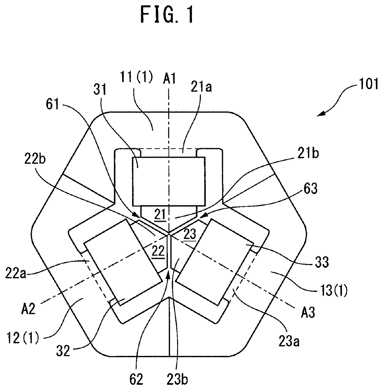
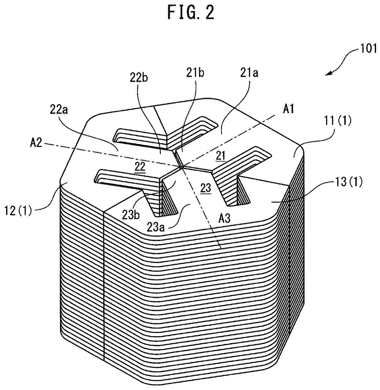
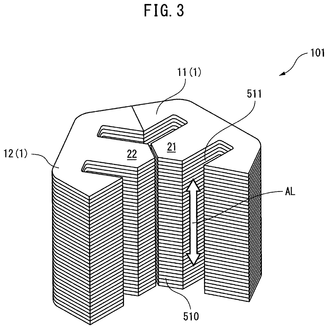
[0023]First, a reactor according to embodiment 1 of the present disclosure will be described. FIG. 1 is a plan view of a reactor 101 according to embodiment 1 of the present disclosure. FIG. 2 is a perspective view of the reactor 101 according to embodiment 1 of the present disclosure. FIG. 3 is a perspective view of a part of the reactor 101 according to embodiment 1 of the present disclosure when separated.

[0024]The reactor 101 according to embodiment 1 of the present disclosure comprises an outer peripheral iron core 1, at least three leg part iron cores (21, 22, 23), and coils (31, 32, 33) which are wound on the respective at least three leg part iron cores (2...


PUM

PropertyMeasurementUnit
circumferenceaaaaaaaaaa
sizesaaaaaaaaaa
depthaaaaaaaaaa

Abstract

A reactor includes an outer peripheral iron core, at least three leg part iron cores arrayed on an inner surface side thereof, each of which is composed of a laminate of a plurality of electromagnetic steel sheets, and coils wound on the respective leg part iron cores, wherein each of the at least three leg part iron cores is arranged so that one end thereof in the direction of a winding axis of the coil is magnetically connected to the outer peripheral iron core and the other end in the direction of the winding axis is magnetically connected to the other end of another of the at least three leg part iron cores via a gap, and at least one of the leg part iron cores includes a weld part for welding at least a part of the plurality of electromagnetic steel sheets in the lamination direction.

Description

BACKGROUND OF THE INVENTION1. Field of the Invention[0001]The present invention relates to a reactor, and in particular, relates to an iron core-type reactor having gaps.2. Description of Prior Art[0002]To date, reactors which comprise an outer peripheral iron core spanning the outer circumference thereof and at least three iron core coils which contact or are connected to the inside of the outer peripheral iron core, and in which each iron core coil is composed of an iron core and a coil wound around the iron core and is magnetically connected to another iron core coil adjacent thereto via a gap have been known. In such conventional reactors, when the iron cores are formed by laminating a plurality of electromagnetic steel sheets, there is a problem in that noise and vibration occur when the reactor is driven.[0003]A three-phase reactor comprising a vibration suppression structure disposed near the gaps to suppress vibration generated in the gaps has been reported (e.g., Japanese U...

Claims


Application Information

Patent Timeline
Patent Type & Authority Applications(United States)
IPC IPC(8): H01F3/14H01F27/30
CPCH01F27/306H01F3/14H01F27/245H01F27/263H01F37/00
Inventor TSUKADA, KENICHIYOSHIDA, TOMOKAZUSHIROUZU, MASATOMO
Owner FANUC LTD
Why Eureka
Try Eureka