Method of reducing or even eliminating the vibration of a rotorcraft lift and propulsion rotor, and an airfoil assembly and a rotor implementing said method

a technology of rotor, which is applied in the direction of propellers, water-acting propulsive elements, wing adjustments, etc., can solve the problems of alternating mechanical stresses, difficult to balance the rotorcraft in level flight, and fatigue phenomenon harmful to materials, so as to reduce or even eliminate the vibration generated by the blades of the lift and propulsion rotor

Inactive Publication Date: 2013-11-12
EUROCOPTER
View PDF16 Cites 0 Cited by
  • Summary
  • Abstract
  • Description
  • Claims
  • Application Information

AI Technical Summary

Benefits of technology

[0017]An object of the present invention is to propose a method that enables the vibration generated by the blades of a lift and propulsion rotor to be reduced or even eliminated.

Problems solved by technology

Consequently, the resultant of the aerodynamic forces exerted on a blade does not have the same value at all azimuth positions, nor does it have the same point of application: the bending moment at the root of the blade is thus high and variable, thereby generating alternating mechanical stresses that give rise to a fatigue phenomenon that is harmful to materials.
Furthermore, the resultant of the aerodynamic forces on all of the blades is no longer carried by the drive axis of the rotor, thereby creating a roll moment, which increases with increasing speed of advance of the rotorcraft and which can make it difficult to balance the rotorcraft in level flight.
It should be observed that the angular moment in drag of a blade about the drag hinge under the effect of inertial forces and aerodynamic forces constitutes a source of vibration and of noise.

Method used


Image

  • Method of reducing or even eliminating the vibration of a rotorcraft lift and propulsion rotor, and an airfoil assembly and a rotor implementing said method
  • Method of reducing or even eliminating the vibration of a rotorcraft lift and propulsion rotor, and an airfoil assembly and a rotor implementing said method
  • Method of reducing or even eliminating the vibration of a rotorcraft lift and propulsion rotor, and an airfoil assembly and a rotor implementing said method

Examples


Embodiment Construction

[0063]Elements that are shown in a plurality of different figures are given the same references in each of them.

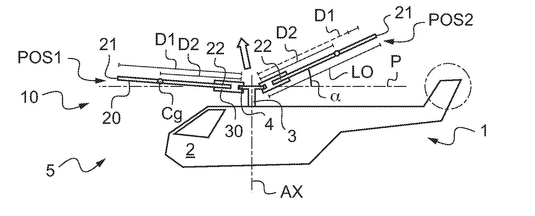
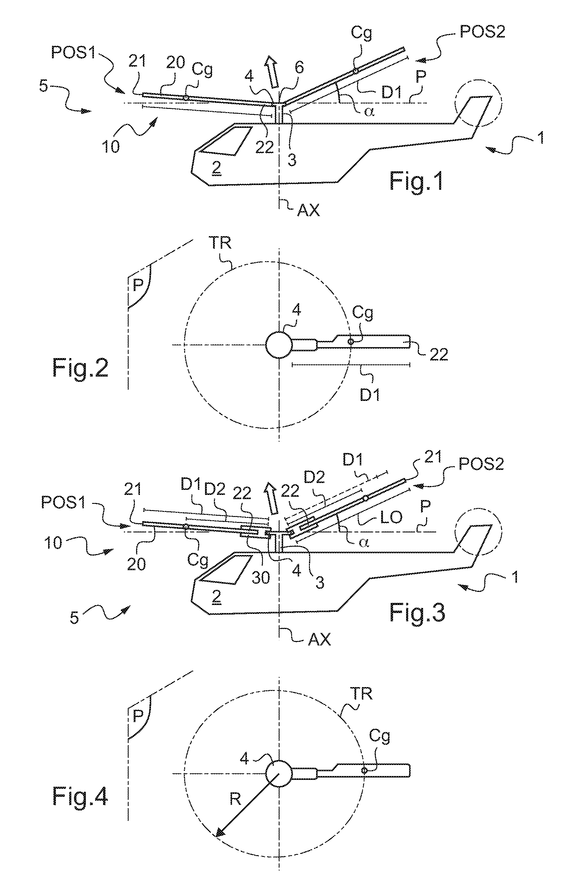
[0064]FIG. 1 shows a rotorcraft 1, and more precisely a helicopter of the prior art.

[0065]The rotorcraft 1 is provided with a fuselage 2 and a rotor 5 providing lift and propulsion to the rotorcraft 1.

[0066]Consequently, the rotor 5 is provided with a mast 3, conventionally referred to as the rotor mast, suitable for being rotated about a drive axis AX by a power plant (not shown).

[0067]The mast 3 is then secured to a hub 6 having a plurality of airfoil assemblies 10 fastened thereto. Under such circumstances, each airfoil assembly 10 comprises a blade 20 extending from a blade root 22 towards a free end 21, the blade root 22 being fastened to the hub 6 by hinge means 4, a laminated elastomer thrust bearing serving in particular to provide the functions of a flapping hinge, a drag hinge, and a pitch hinge, e.g. about a flapping axis, a drag axis, and a pitch axis.

[0068]It ...


PUM


Abstract

The present invention relates to a method of reducing the vibration of a lift and propulsion rotor (5) of a rotorcraft (1), the rotor having a plurality of airfoil assemblies (10) that perform rotary movement around a drive axis (AX) of the rotor (5), each airfoil assembly (10) comprising a blade (20) extending longitudinally from a root (22) suitable for being fastened to hinge means (4) of a hub (6) of said rotor (5) to a free end (21), a first distance (D1) extending between said free end (21) and said hinge means (4). In the method, said first distance (D1) is caused to vary cyclically so that the projection (TR) of the center of gravity (Cg) of a blade (20) on a horizontal plane (P) perpendicular to said drive axis (AX) and containing said hinge means (4) describes a circle.

Description

CROSS REFERENCE TO RELATED APPLICATION[0001]This application claims the benefit of FR 09 03706 dated Jul. 28, 2009, the disclosure of which is incorporated herein by reference.FIELD OF THE INVENTION[0002]The present invention relates to a method of reducing, or even eliminating, the vibration of a rotorcraft lift and propulsion rotor, and it also relates to an airfoil assembly and to a rotor implementing said method.[0003]The technical field of the invention is that of methods and means for attenuating rotor vibration as caused by the drag movements of a blade.BACKGROUND OF THE INVENTION[0004]In general, rotorcraft lift rotors comprise a hub driven in rotation about a drive axis by an outlet shaft of a main gearbox, referred to as a drive shaft, and at least two blades that are fastened to the hub via suitable hinges. For example, each blade has a sleeve that is hinged to the hub by means of a laminated elastomer thrust bearing.[0005]It is recalled that assuming that each blade is e...

Claims


Application Information

Patent Timeline
Patent Type & Authority Patents(United States)
IPC IPC(8): B64C11/28
CPCB64C27/001B64C27/48B64C27/54B64C27/72Y02T50/34Y02T50/30
Inventor HERPIN, GILLES
Owner EUROCOPTER
Why Eureka
Try Eureka