
Bicycle tire

a technology for bicycles and tires, applied in the field of bicycle tires, can solve the problems of inconvenient use, heavy discomfort for users, and desperate need for punctures, and achieve the effect of reducing the incidence of safety accidents

Active Publication Date: 2014-07-08
TANNUS CO LTD
View PDF2 Cites 8 Cited by
  • Summary
  • Abstract
  • Description
  • Claims
  • Application Information

AI Technical Summary

Benefits of technology

The present invention provides a bicycle tire that can prevent separation from the rim and be comfortable to drive on the floor surface when grounded. This is achieved through the use of stoppers that are held securely in place by annular holding protrusions on the rim, reducing the risk of safety accidents during running.

Problems solved by technology

Recently, with the spread of awareness on eco-friendly and low carbon materials, urban bicycles and mountain bicycles have been widely spread, and the generally used bicycles with built-in tubes have several inconveniences in that they are highly concerned about puncture and in that users have to pump air into the tires because of a leakage of air injected into the tubes as time passes.
Moreover, in the case of the mountain bicycles, the users may experience heavy discomfort because there is no way to properly cope with puncture of the tire when it has a puncture because the mountain bicycles run in a mountain area spaced apart from a downtown area, and hence, development of a bicycle tire which can prevent the puncture is in desperate need.
However, if an impact is eccentrically applied to the right or left direction during running in a state where the tire is mounted on a rim of the bicycle, a rim fixing part of the tire may be separated from the rim, and it may cause the incidence of safety accidents, and hence, development of bicycle tires, which can solve such a problem, is urgently needed.

Method used


Image

  • Bicycle tire
  • Bicycle tire
  • Bicycle tire

Examples


Embodiment Construction

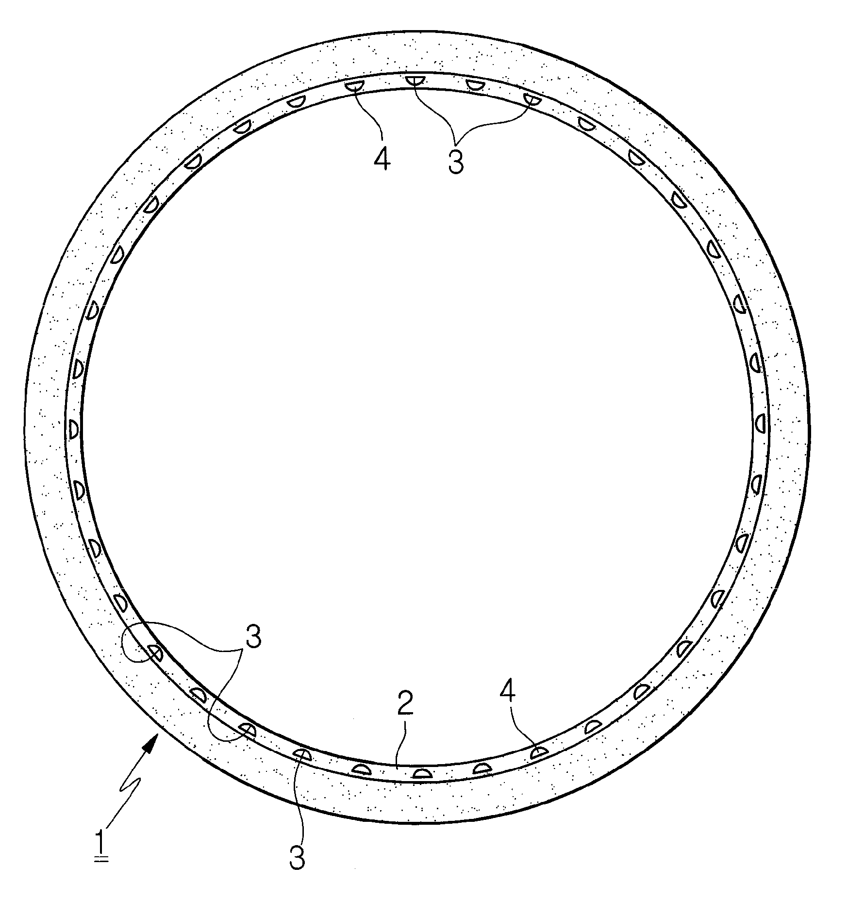
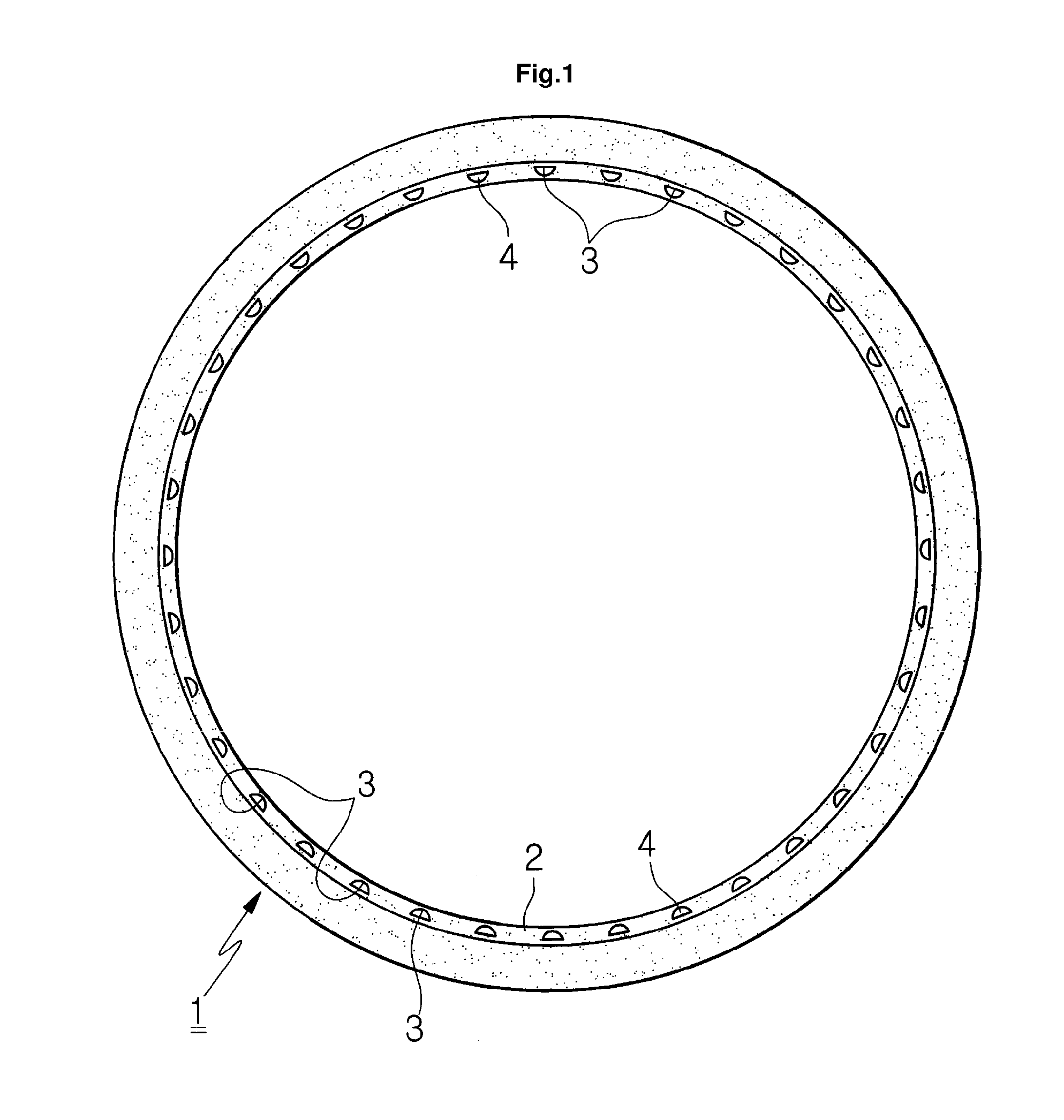
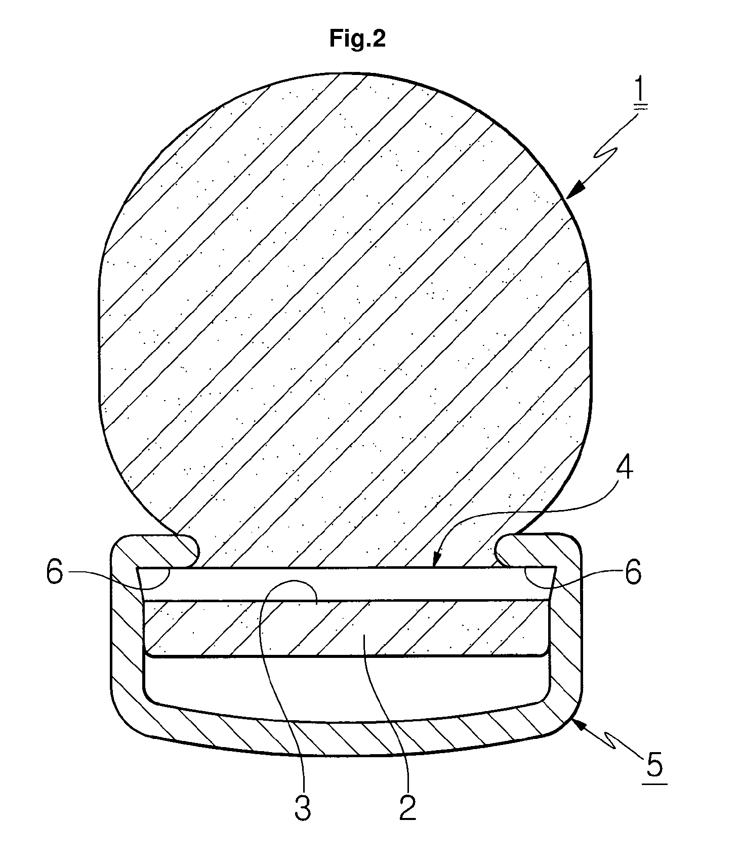
[0013]Reference will be now made in detail to a bicycle tire 1 of the present invention with reference to the attached drawings. FIG. 1 is a front view showing a structure of a bicycle tire according to the present invention, FIG. 2 is an enlarged sectional view showing a state where the bicycle tire is mounted to the bicycle rim, and FIG. 3 is an exploded perspective view of stoppers fixed in coupling holes of the bicycle tire.

[0014]The bicycle tire 1 manufactured by injection-foam molding includes: a plurality of coupling holes 3 formed in a rim coupling portion 2 of the bicycle tire 1 at predetermined intervals; and stoppers 4 formed of synthetic resin materials and forcedly fit to the coupling holes 3 so that the stoppers 4 are stopped by annular holding protrusions 6 and can keep a firm mounted state when the bicycle tire 1 is mounted to the bicycle rim.

[0015]That is, the rim coupling portion 2 of the tire 1 has the annular holding protrusions formed on the inner circumference ...


PUM


Abstract

The present invention relates to a bicycle tire. More particularly, the bicycle tire is formed by foaming synthetic resin materials and is mounted to a rim of a bicycle, wherein the tire is prevented from being unexpectedly separated from the rim in use. That is, the bicycle tire formed by injection-foam molding is characterized in that: a rim coupling portion of the bicycle tire is formed with a plurality of coupling holes at predetermined intervals; and stoppers formed of synthetic resin materials are fixed in the coupling holes, stopped by annular holding protrusions when the tire is mounted to the bicycle rim, and formed of arch surfaces, horizontal surfaces and tilted both end surfaces so that the tilted both end surfaces are protruded when the stoppers are fixed to the coupling holes.

Description

REFERENCE TO RELATED APPLICATIONS[0001]This is a continuation of pending International Patent Application PCT / KR2010 / 001405 filed on Mar. 5, 2010, which designates the United States and claims priority of Korean Application No. 10-2009-0066905 filed on Jul. 22, 2009, the entire contents of which are incorporated herein by reference.FIELD OF THE INVENTION[0002]The present invention relates to a bicycle tire, and more particularly, to a bicycle tire, which is formed by foaming synthetic resin materials and is mounted to a rim of a bicycle, wherein the tire is prevented from being unexpectedly separated from the rim in use.BACKGROUND OF THE INVENTION[0003]Recently, with the spread of awareness on eco-friendly and low carbon materials, urban bicycles and mountain bicycles have been widely spread, and the generally used bicycles with built-in tubes have several inconveniences in that they are highly concerned about puncture and in that users have to pump air into the tires because of a l...

Claims


Application Information

Patent Timeline
Patent Type & Authority Patents(United States)
IPC IPC(8): B60C19/00
CPCB60C7/105B60C7/24B60C2200/12B60C15/02B60C15/00
Inventor LEE, SUNG, YULL
Owner TANNUS CO LTD
Learn More