Compressor intake muffler and filter

a compressor and intake muffler technology, applied in the field of compressors, can solve the problems of unacceptably noisy compressors, noisy compressors which are mobile or portable and not enclosed in a cabinet or compressor room, and can generate high noise output during operation

Active Publication Date: 2014-07-08
BLACK & DECKER INC
View PDF148 Cites 18 Cited by
  • Summary
  • Abstract
  • Description
  • Claims
  • Application Information

AI Technical Summary

Benefits of technology

[0016]In an embodiment, a compressor assembly can have a means for sound control of a feed air path which uses a means for dampening sound emitted from a pump system through the feed air path.

Problems solved by technology

Existing compressors can generate a high noise output during operation.
This noise can be annoying to users and can be distracting to those in the environment of compressor operation.
Compressors which are mobile or portable and not enclosed in a cabinet or compressor room can be unacceptably noisy.
However, entirely encasing a compressor, for example in a cabinet or compressor room, is expensive, prevents mobility of the compressor and is often inconvenient or not feasible.
Additionally, such encasement can create heat exchange and ventilation problems.
When a power source for a compressor is electric, gas or diesel, unacceptably high levels of unwanted heat and exhaust gases can be produced.
Additionally, existing compressors can be inefficient in cooling a compressor pump and motor.
The use of multiple fans adds cost manufacturing difficulty, noise and unacceptable complexity to existing compressors.
Current compressors can also have improper cooling gas flow paths which can choke cooling gas flows to the compressor and its components.

Method used


Image

  • Compressor intake muffler and filter
  • Compressor intake muffler and filter
  • Compressor intake muffler and filter

Examples


example 1

[0129]FIG. 19 is a first table of example performance characteristics for an example embodiment. FIG. 19 contains combinations of performance characteristics exhibited by an embodiment of compressor assembly 20.

example 2

[0130]FIG. 20 is a second table of example performance characteristics for an example embodiment. FIG. 20 contains combinations of further performance characteristics exhibited by an embodiment of compressor assembly 20.

example 3

[0131]FIG. 21 is a table containing a third example of performance characteristics of an example compressor assembly 20. In the Example of FIG. 21, a compressor assembly 20 having an air ducting shroud 485, a dampening ring 700, an intake muffler 900, four sound control chambers, a fan cover, four foam sound absorbers and a tank seal 600 exhibited the performance values set forth in FIG. 21.

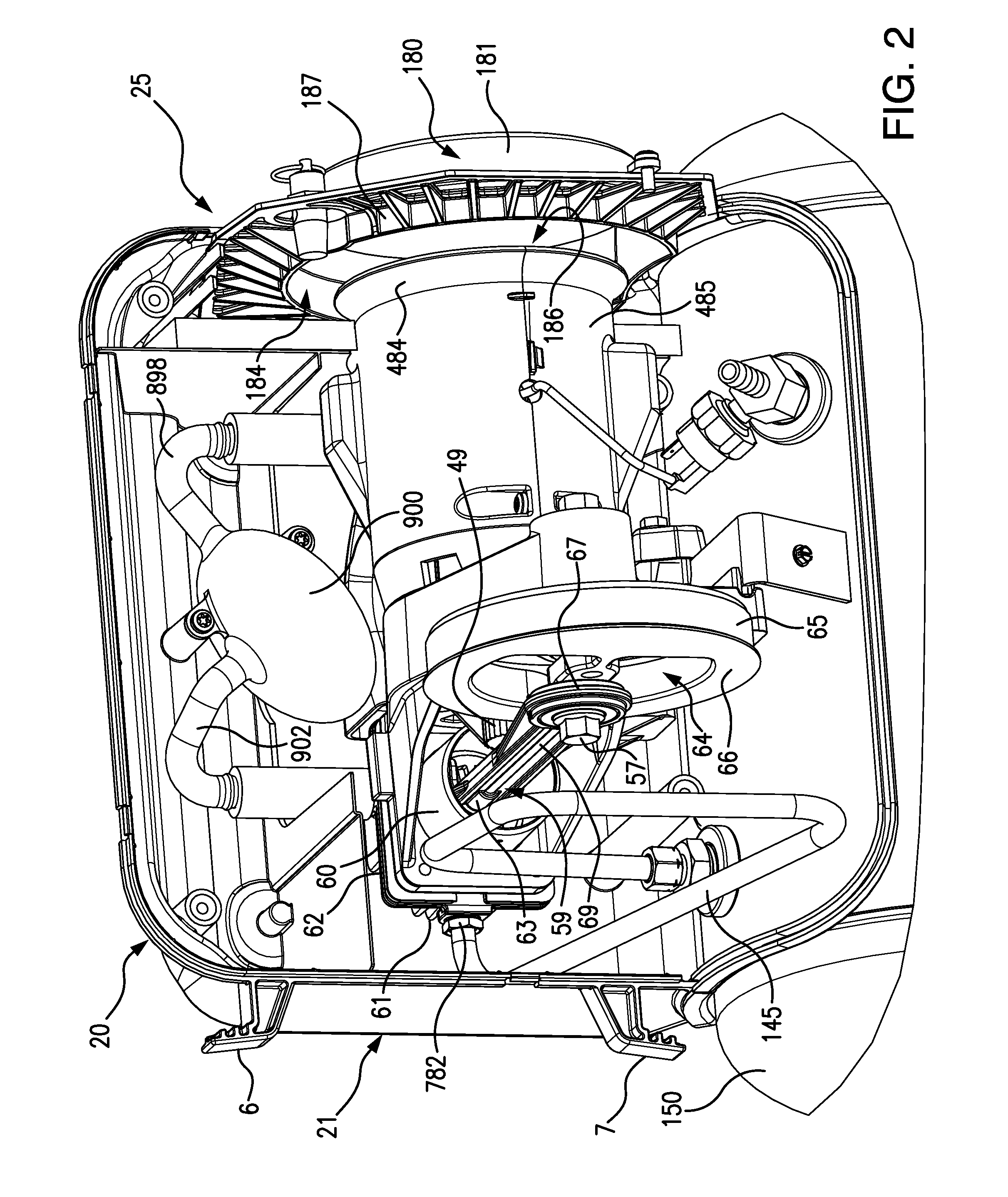
[0132]FIGS. 22 and 23 illustrate a top view of a feed air system 905 having an intake muffler 900 (also herein as “compressor intake muffler 900” or “muffler 900”).

[0133]The feed air system 905 can feed air to be compressed along the feed air path 922 (FIG. 23) from a feed air port 952 to the cylinder head 61. In an embodiment, air can be fed from an optional inertia filter 949 which can be present in the air ducting shroud 485 (FIG. 22). In an embodiment, the intake muffler 900 can be in the feed path to the cylinder head 61. In an embodiment, the air ducting shroud 485 is optional. In an embodi...


PUM

PropertyMeasurementUnit
angleaaaaaaaaaa
angleaaaaaaaaaa
pressureaaaaaaaaaa

Abstract

A muffler for a feed air system of a compressor assembly. The muffler can be a product of a blow molding process and used in a method of sound control for a compressor assembly. A method of controlling sound in a compressor assembly can have the step of providing a feed air and the step of providing the muffler an outlet in communication with an inlet of a pump assembly which can compress the feed air fed through the muffler and into the pump assembly. Sound control for a compressor assembly is also accomplished by adapting a feed air system to have sound control of a feed air path by dampening the sound emitted from a pump system through the feed air path.

Description

CROSS-REFERENCE TO RELATED APPLICATIONS[0001]This patent application claims benefit of the filing date under 35 USC §120 of copending U.S. provisional patent application No. 61 / 533,993 entitled “Air Ducting Shroud For Cooling An Air Compressor Pump And Motor” filed on Sep. 13, 2011. This patent application claims benefit of the filing date under 35 USC §120 of copending U.S. provisional patent application No. 61 / 534,001 entitled “Shroud For Capturing Fan Noise” filed on Sep. 13, 2011. This patent application claims benefit of the filing date under 35 USC §120 of copending U.S. provisional patent application No. 61 / 534,009 entitled “Method Of Reducing Air Compressor Noise” filed on Sep. 13, 2011. This patent application claims benefit of the filing date under 35 USC §120 of copending U.S. provisional patent application No. 61 / 534,015 entitled “Tank Dampening Device” filed on Sep. 13, 2011. This patent application claims benefit of the filing date under 35 USC §120 of copending U.S. p...

Claims


Application Information

Patent Timeline
Patent Type & Authority Patents(United States)
IPC IPC(8): F02M35/00
CPCF04B39/0055F04B39/0061F04B23/10F04B39/0027F04B41/02F04B39/121F04B35/06F04B39/0033F04B39/066F04D19/00F04D29/668Y10S181/403Y10T29/49238Y10T137/7039F04B35/04F04B9/02
Inventor WOOD, MARK W.VOS, STEPHEN J.CRAIG, SCOTT D.
Owner BLACK & DECKER INC
Why Eureka
Try Eureka