Liquid container and apparatus in which liquid container is mountable

a liquid container and apparatus technology, applied in printing and other directions, can solve the problems of large ink capacity, difficulty in providing robust images, and low light and gas resistance of dye ink, and achieve the effect of increasing the size or cost of the liquid container and efficient stirring

Active Publication Date: 2014-07-08
CANON KK
View PDF21 Cites 48 Cited by
  • Summary
  • Abstract
  • Description
  • Claims
  • Application Information

AI Technical Summary

Benefits of technology

[0012]The present invention provides a liquid container and an apparatus in which the liquid container is mountable, the liquid container and the apparatus allowing a liquid to be efficiently stirred without depending on the shape of the liquid container or the mounted orientation of the liquid container or increasing the size or cost of the liquid container.
[0032]The present invention includes the first and second openings opening into the liquid containing chamber so as to be misaligned with each other in the direction of gravitational force in the installed orientation of the liquid container. The present invention can thus generate a liquid flow which efficiently stirs the liquid in the ink containing chamber, through the communication path allowing the first and second openings to communicate with each other. That is, since the first and second openings are positioned so as to be misaligned with each other in the vertical direction, a vertical flow can be generated, through the channel, between a portion of the liquid located in the lower part of the liquid containing chamber and having a relatively high concentration and a portion of the liquid located in the upper part of the liquid containing chamber and having a relatively low concentration. Furthermore, besides the liquid supply path, the communication path is provided which allows the first and second openings opening into the liquid containing chamber to communicate with each other. Thus, a flow of the liquid which efficiently stirs the liquid in the ink containing chamber can be generated without depending on the pressure of the liquid in the supply path.
[0033]For example, in an ink tank containing, as a liquid, ink containing pigment, a lower portion of the ink having a high pigment concentration is drawn in through the first opening. The drawn-in ink is then guided, through the second opening, to an upper portion of the ink having a low pigment concentration. This allows the pigment ink to be efficiently stirred.

Problems solved by technology

In particular, printers for graphic art such as posters involve a large amount of ink supplied per sheet and thus require a large ink capacity.
In general, dye ink offers only low light and gas resistance and thus has difficulty providing robust images.
Hence, printed images may be subjected to color differences or color unevenness and offer degraded color stability and color reproducibility.
This may preclude ink containing pigment from being efficiently stirred.
For example, if the ink containing chamber extends a long distance along the direction of gravitational force and the buffer chamber is provided in the ink supply path between the ink supply port and an opening positioned at the bottom of the ink containing chamber, then sufficient stirring performance cannot be provided when the volume of the buffer chamber decreases at a low speed.
That is, the ink flow squirted from the buffer chamber through the ink supply port and the opening toward an inner upper part of the ink containing chamber loses force and may fail to reach the inner upper part of the ink containing chamber.
That is, ink squirted horizontally through the opening is provided to ink with the same pigment concentration and fails to act positively on ink with different pigment concentrations.
Thus, in particular, an ink area with a low pigment concentration which is present in the inner upper part of the ink containing chamber is difficult to stir efficiently.
However, the increased volume of the buffer chamber increases the size of the ink tank.
This results in the need to improve the capabilities of a pressurization pump on the printing apparatus side configured to supply the pressurized air, leading to increased size and cost of the printing apparatus.
This may increase the size and cost of the ink tank.

Method used


Image

  • Liquid container and apparatus in which liquid container is mountable
  • Liquid container and apparatus in which liquid container is mountable
  • Liquid container and apparatus in which liquid container is mountable

Examples


first embodiment

(First Embodiment)

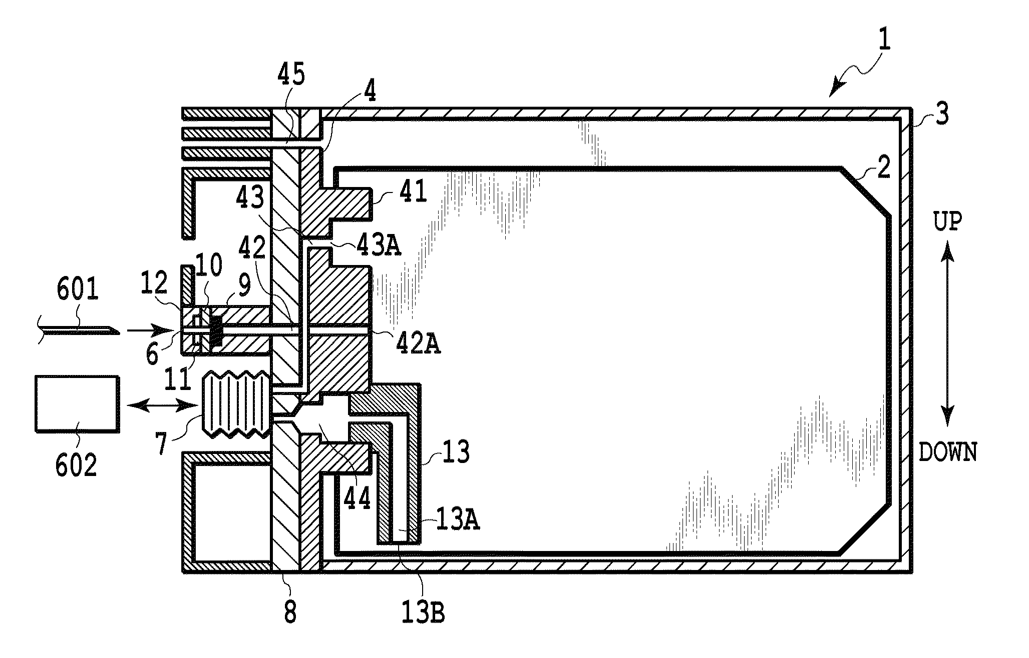
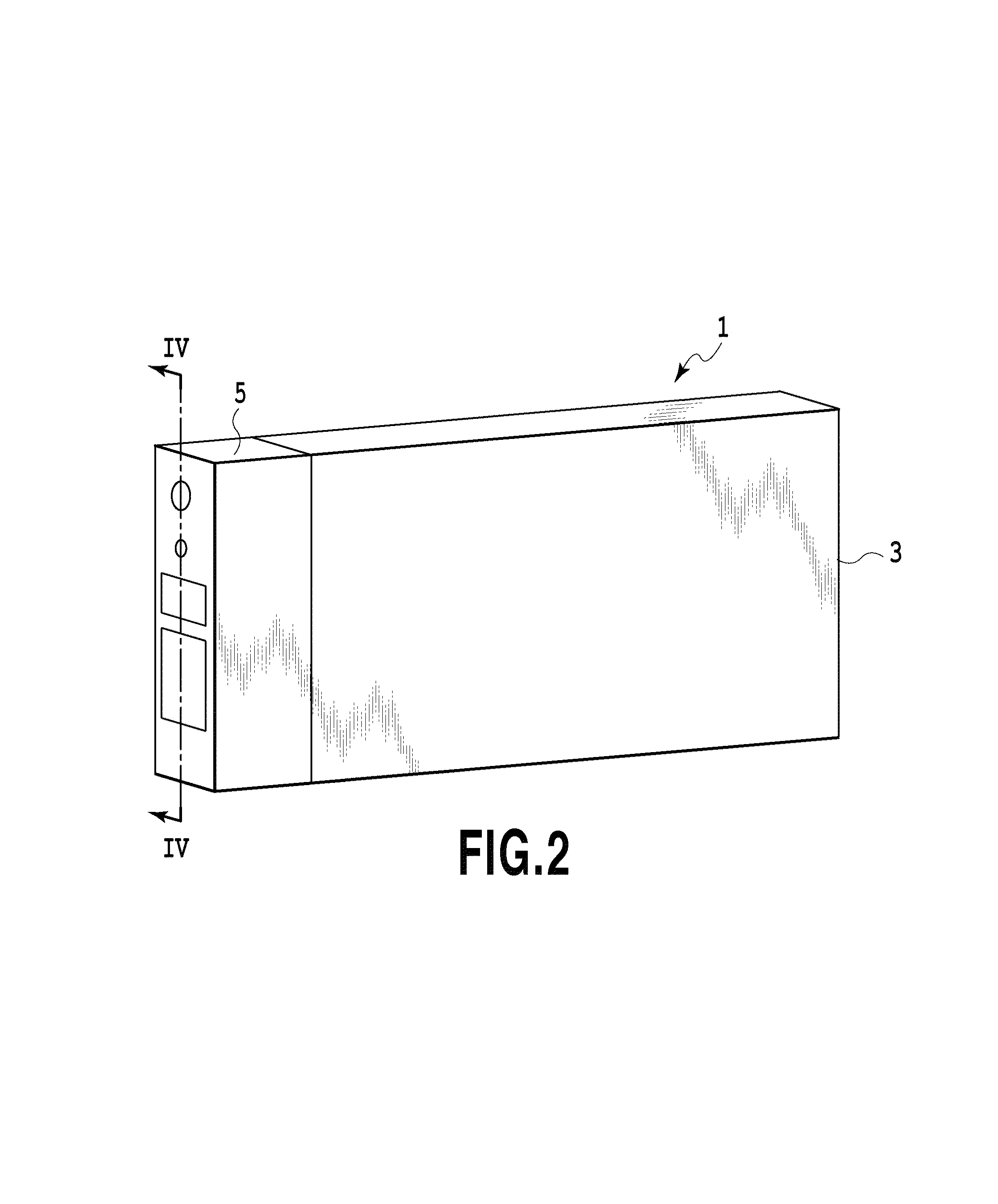
[0054]FIG. 1 to FIG. 8 are diagrams illustrating a first embodiment of the present invention. The present embodiment will be described below for each of a plurality of items. Furthermore, the liquid container according to the present embodiment is an example of application of the present invention as an ink tank which accommodates ink and which is mountable in a printing apparatus.
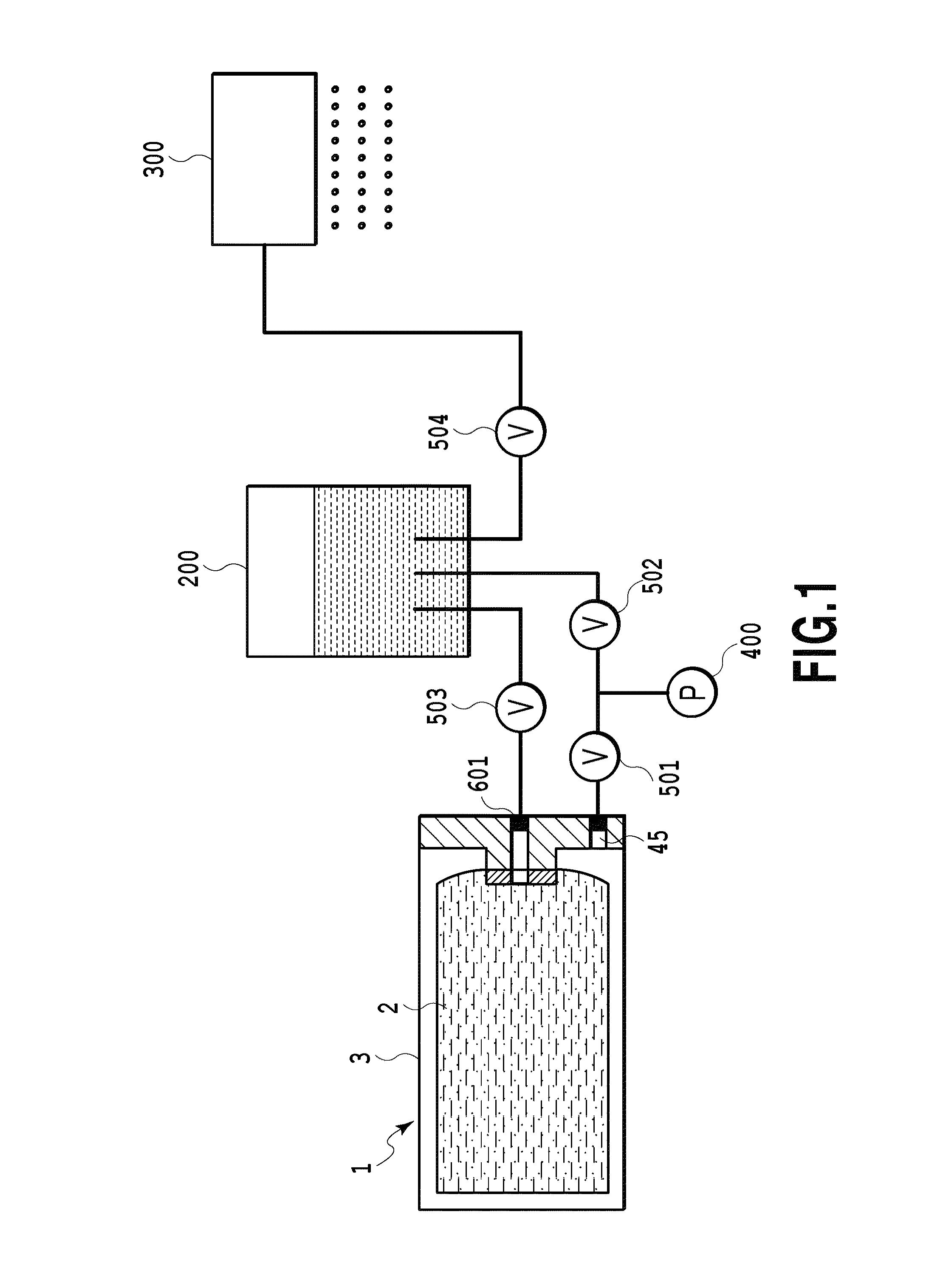
(Ink Supply System)

[0055]FIG. 1 is a schematic diagram of an ink supply system of a printing apparatus in which an ink tank 1 according to the present embodiment is mountable. Ink in the ink tank (ink containing chamber) 1 can be supplied to an ink jet print head 300 through a sub-tank 200. A power source for ink supply is compressed air from a pressurization pump 400 provided in the printing apparatus. As described below, the ink tank 1 and the sub-tank 200 are pressurized to allow ink to be supplied. A channel between the ink tank 1 and the sub-tank 200 and the print head 300 and the pr...

second embodiment

(Second Embodiment)

[0079]Now, a second embodiment of the present invention will be described based on FIG. 9 to FIG. 11.

[0080]The ink tank 1 according to the present embodiment includes a one-way valve provided between the intake channel 13A and the intake hole 44 to regulate the flow of ink to one direction. Moreover, a diaphragm valve (displacement valve) 18 is provided in the channel between the stirring hole 43 and the pump chamber 7 to detect a flow of ink. The remaining part of the configuration of the ink tank 1 according to the present embodiment is similar to the corresponding part of the configuration of the first embodiment.

[0081]The configuration of the one-way valve 16 and the diaphragm valve 18 and the ink stirring operation will be described below.

(One-Way Valve)

[0082]FIG. 11 is an enlarged exploded perspective view of the one-way valve 16. A disc-shaped circular disc member 15 is disposed between the intake hole 44 and the intake channel 13A. The disk member 15 funct...

third embodiment

(Third Embodiment)

[0091]As shown in FIG. 12, the ink tank 1 according to the present embodiment includes a one-way valve 17 in the stirring hole 43 in the ink tank according to the second embodiment, and is similar to the ink tank according to the embodiment in the other respects. The one-way valve 16 on the intake hole 44 side is hereinafter referred to as the “first one-way valve”. The one-way valve 17 on the stirring hole 43 side is hereinafter referred to as the “second one-way valve”. The second one-way valve 17 is configured similarly to the first one-way valve 16. The second one-way valve 17 includes the disc member 15 movably provided, as a valve disc, in the space between the stirring hole 43 and a cylindrical presser member 14 attached to the opening of the stirring hole 43. A step similar to the step of the recess portion 441 in FIG. 11 is formed in an opposite portion of the presser member 14 which lies opposite the disc member 15. This ensures a flow of ink from the sti...


PUM


Abstract

A liquid container enables a liquid contained in a liquid containing chamber to be supplied to an exterior through a supply port. The liquid container includes a first channel, a second channel, and a communication path. The first channel is in communication with a first opening which opens into the liquid containing chamber. The second channel is in communication with a second opening which opens into the liquid containing chamber, the second opening being positioned above the first opening in a direction of gravitational force. The communication path allows the first channel and the second channel to communicate with each other outside the liquid containing chamber to permit a flow of the liquid.

Description

BACKGROUND OF THE INVENTION[0001]1. Field of the Invention[0002]The present invention relates to a liquid container which can contain various liquids and an apparatus in which the liquid container is mountable. In particular, the present invention relates to a liquid container which is preferably used as an ink tank containing pigment ink, and an apparatus in which the liquid container is mountable and which is preferably used as a printing apparatus printing images using the pigment ink fed from the ink tank.[0003]2. Description of the Related Art[0004]An exemplary supply system for a print head of an ink jet printing apparatus is configured such that an ink tank which accommodates ink is removably connected to a terminal of the supply system. Known removable ink tanks include those which hold ink using a capillary force generating member such as a sponge provided inside the tank and those which hold ink directly inside a flexible bag or a rigid housing. In particular, printers for...

Claims


Application Information

Patent Timeline
Patent Type & Authority Patents(United States)
IPC IPC(8): B41J2/175
CPCB41J2/17556B41J2/17509B41J2002/17516
Inventor NANJO, TATSUOKOTAKI, YASUOTAKADA, HITOSHIKUBO, KOICHIOGURA, HIDEKIMURAKAMI, HIRONORIMIYASHITA, TAKEHOFUKAZAWA, HIDEOADACHI, EIICHI
Owner CANON KK
Why Eureka
Try Eureka