Receiving apparatus and method, program, and receiving system
a technology of receiving apparatus and receiving system, applied in the direction of amplitude demodulation, television system, pulse technique, etc., can solve the problem of failure of decoding by a subsequent decoder
- Summary
- Abstract
- Description
- Claims
- Application Information
AI Technical Summary
Benefits of technology
Problems solved by technology
Method used
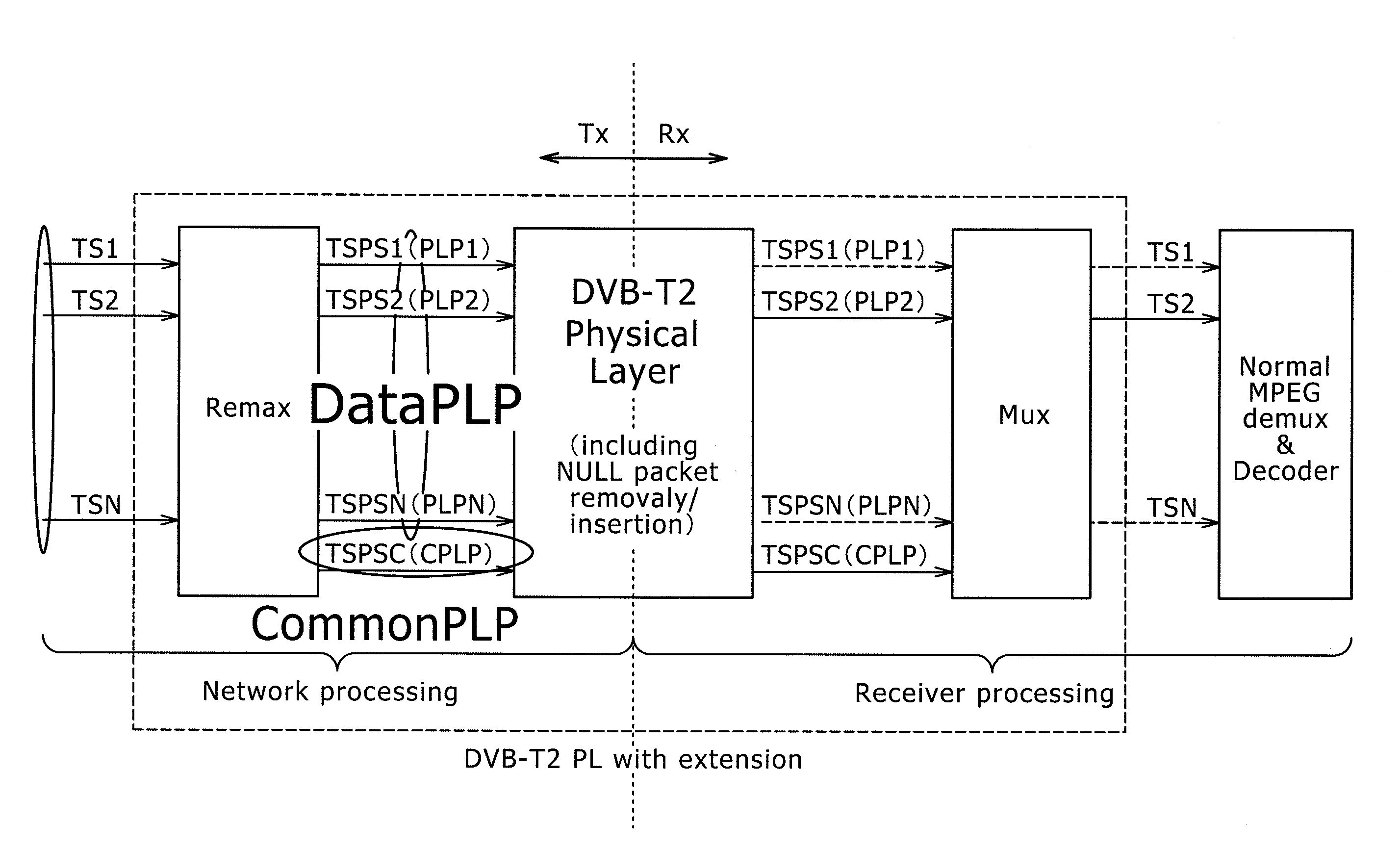
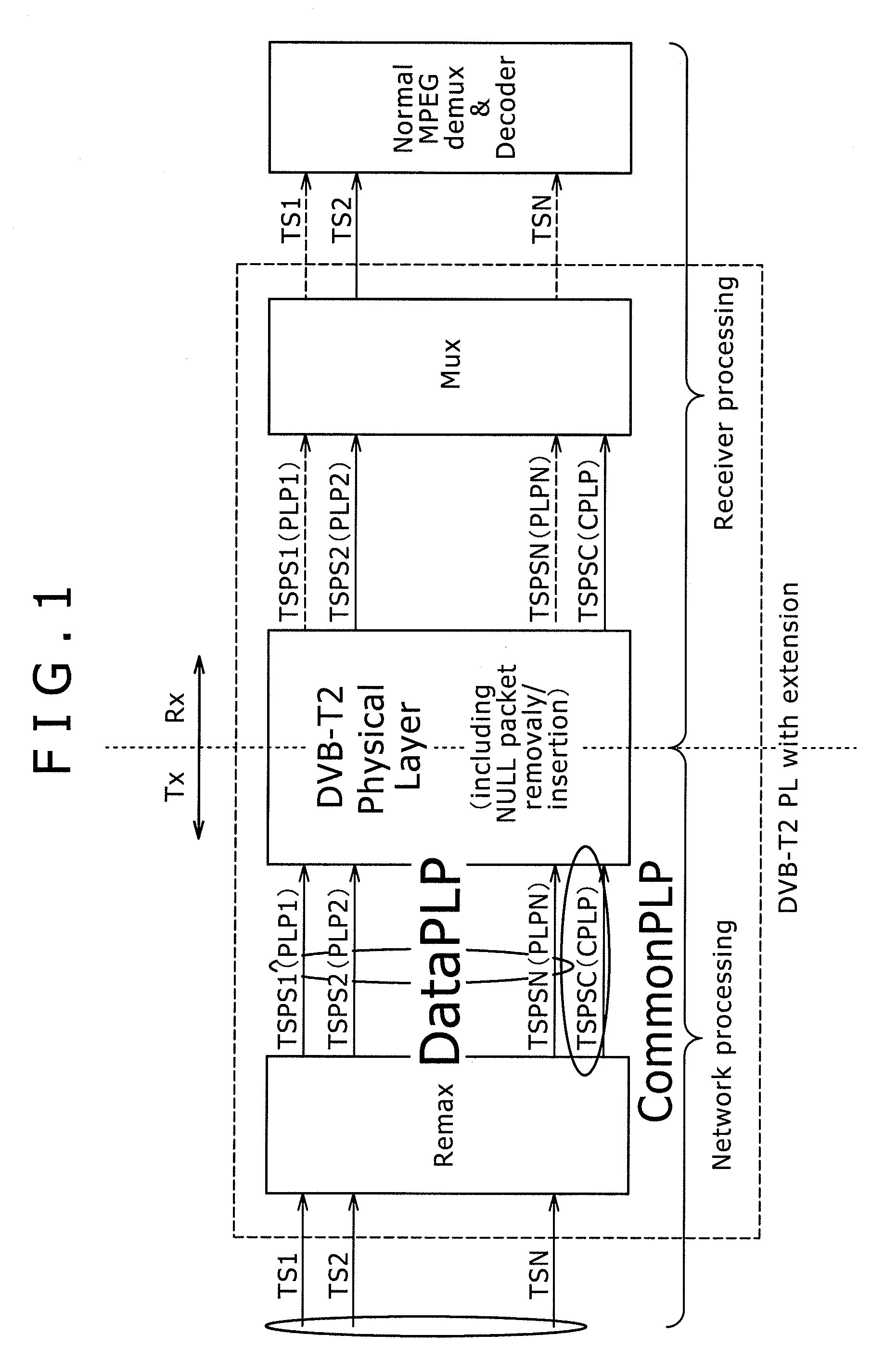
Image

Examples
first embodiment
[0182]FIG. 15 shows a configuration example of a receiving system practiced as the invention.
[0183]As shown in FIG. 15, the receiving system is configured by an acquisition section 201, a transmission path decode processing section 202, and an information source decode processing section 203, for example.
[0184]The acquisition section 201 obtains signals via transmission paths, not shown, such as terrestrial digital broadcasting, satellite digital broadcasting, a CATV (Cable Television) network, the Internet, and other networks and supplies the received signals to the transmission path decode processing section 202.
[0185]If signals are broadcast from a broadcasting station on the terrestrial wave, the satellite wave, or the CATV (Cable Television), for example, the acquisition section 201 is configured by a tuner, an STB (Set-top Box), and so on like the acquisition section 12 shown in FIGS. 12A and 12B. If signals are transmitted from a Web server in a multicast manner like IPTV (In...
second embodiment
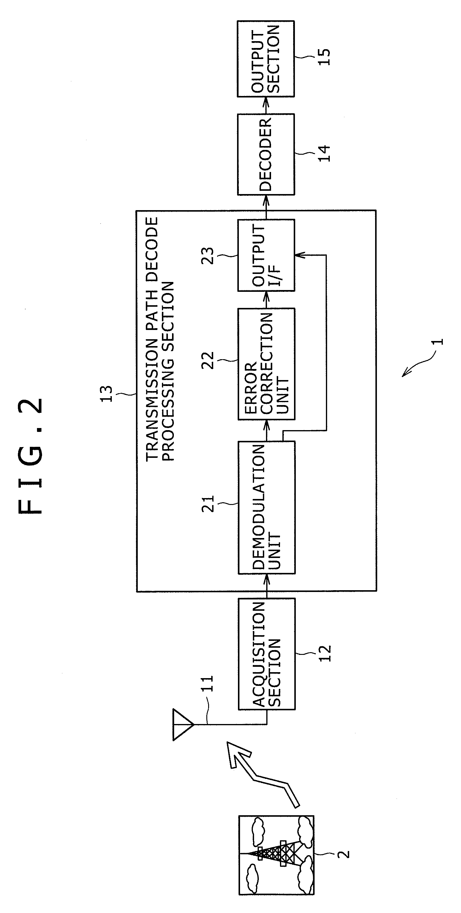
[0200]FIG. 16 shows a configuration example of a receiving apparatus practiced as the invention.
[0201]With reference to FIG. 16, components similar to those previously described with reference to FIG. 15 are denoted by the same reference numerals and the description thereof will be appropriately omitted.
[0202]The receiving system shown in FIG. 16 is the same as the receiving system shown in FIG. 15 in having an acquisition section 201, a transmission path decode processing section 202, and an information source decode processing section 203, but different in additionally having an output section 211.
[0203]The output section 211 is a display apparatus for displaying images or a loudspeaker for outputting sound, for example, and outputs images or sound as a signal outputted from the information source decode processing section 203.
[0204]The receiving system configured as described above, is applicable to television receivers for receiving television broadcasting as digital broadcastin...
third embodiment
[0206]FIG. 17 shows a configuration example of a receiving system practiced as the invention.
[0207]With reference to FIG. 17, components similar to those previously described with reference to FIG. 16 are denoted by the same reference numerals and the description thereof will be appropriately omitted.
[0208]The receiving system shown in FIG. 17 is the same as the receiving system shown in FIG. 15 in having an acquisition section 201 and a transmission path decode processing section 202.
[0209]However, the receiving system shown in FIG. 17 is different from the receiving system shown in FIG. 15 in that the information source decode processing section 203 is not arranged and a recoding section 221 is arranged.
[0210]The recording block 221 records (or stores) signals (TS packets of MPEG TS for example) outputted from the transmission path decode processing section 202 to a recording (or storage) medium, such as an optical disk, a hard disk (or magnetic disk), and a flash memory, for exam...
PUM
 Abstract
Description
Claims
Application Information
 - R&D
- Intellectual Property
- Life Sciences
- Materials
- Tech Scout
- Unparalleled Data Quality
- Higher Quality Content
- 60% Fewer Hallucinations
Browse by: Latest US Patents, China's latest patents, Technical Efficacy Thesaurus, Application Domain, Technology Topic, Popular Technical Reports.
© 2025 PatSnap. All rights reserved.Legal|Privacy policy|Modern Slavery Act Transparency Statement|Sitemap|About US| Contact US: help@patsnap.com