Pedicle locator instrument

a technology for locators and pedicles, applied in instruments, diagnostic recording/measuring, applications, etc., can solve the problems of wasting valuable operative time, affecting patient safety, and inaccurate placement of pedicles, so as to achieve efficient and accurate locators and patient safety.

Active Publication Date: 2014-07-08
BUONO LEE M
View PDF10 Cites 3 Cited by
  • Summary
  • Abstract
  • Description
  • Claims
  • Application Information

AI Technical Summary

Benefits of technology

[0004]It is the object of the present invention to provide a manually operated pedicle locator instrument which is effective in efficiently and accurately locating pedicles in various types of bony vertebral structures in a non-invasive manner which is patient safe.
[0005]Specifically, the manually operated pedicle locator instrument of the present invention measures the static permittivity of matter to locate pedicles in vertebral or bony structures. The locator senses and compares the dielectric constants of the pedicle and the surrounding matter. When the operative component of the locator, the component which contains controlled capacitors, is placed over non-pedicle material, the locator will sense one dielectric constant. However, when it is placed over a pedicle, there is a different dielectric constant. The locator operates on this capacitance difference generated by differences in density. Circuitry in the locator senses this change and sends the change signal to indicator lights located on the locator. A switch on the locator allows the surgeon to select different levels of capacitance in order to identify thicknesses of different bony structures, i.e. structures in cervical, thoracic, and lumbar vertebral bodies.

Problems solved by technology

However, many surgeons are apprehensive when they must determine the proper placement of pedicle screws.
Inaccurate placement greatly enhances the risk of screw malposition and other significant anatomical circumstances during surgery.
However, this process wastes valuable operative time and is done at great expense.
It also increases patient risk of infection, pressure sores, blood loss, and the accompanying risks associated with general anesthesia.
Prolonged exposure to fluoroscopic x-ray may also result in radiation burn and genetic mutation, resulting in malignancies.

Method used


Image

  • Pedicle locator instrument
  • Pedicle locator instrument
  • Pedicle locator instrument

Examples


Embodiment Construction

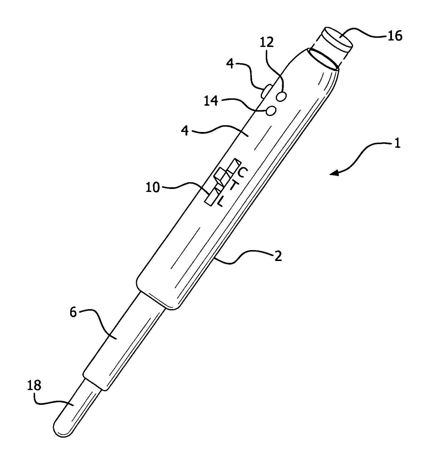
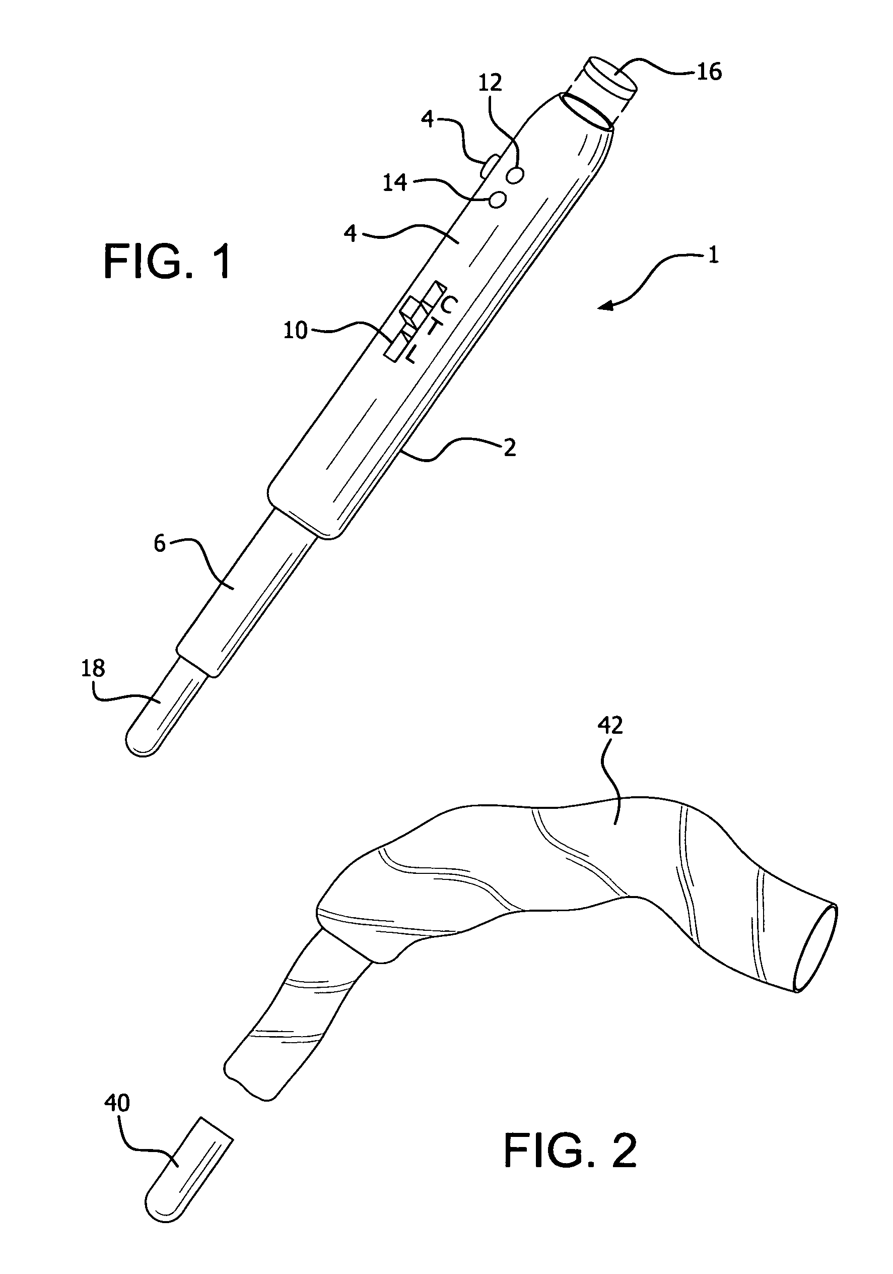
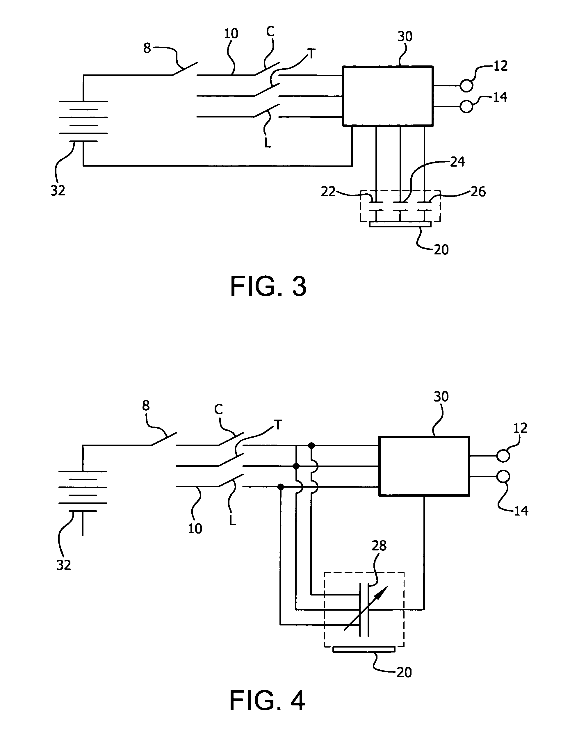
[0011]Pedicle locator 1 is a unitary, self-contained instrument comprising elongated casing 2 with handle section 4 and pedicle detecting section 6. Handle section 4 comprises on / off switch 8, detection selection switch 10, LED indicator lights 12 (red) and 14 (green), and removeable casing cover 16 for the insertion of batteries 32 into casing 2. Detection selection switch 10 has three settings: C for cervical, T for thoracic, and L for lumbar.

[0012]Pedicle detecting section 6 comprises tip portion 18 which houses capacitor sensing component 20 and capacitors 22, 24 and 26 (FIGS. 3) and 28 (FIG. 4), which detect the change in capacitance of the capacitor sensing component. Pedicle detecting section 6 also houses circuit board 30 and the electronic circuitry which communicates the pedicle detecting section to on / off switch 8, detection selection switch 10, and indicator lights 12 and 14. The circuitry operates to provide the requisite signals to illuminate indicator. lights 12 and 1...


PUM


Abstract

A manually operated pedicle locator instrument measures the static permittivity of matter to locate pedicles in vertebral or bony structures. The locator senses and compares the dielectric constants of the pedicle and the surrounding matter. When the operative component of the locator, the component which contains controlled capacitors, is placed over non-pedicle material, the locator will sense one dielectric constant. However, when it is placed over a pedicle, there is a different dielectric constant. The locator operates on this capacitance difference generated by differences in density. Circuitry in the locator senses this change and sends the change signal to indicator lights located on the locator. A switch on the locator allows the surgeon to select different levels of capacitance in order to identify thicknesses of different bony structures, i.e. structures in cervical, thoracic, and lumbar vertebral bodies.

Description

BACKGROUND OF THE INVENTION[0001]Pedicle fixation is a common means to repair and attach vertebra relative to each other. It generally involves the insertion of a pedicle screw in two or more adjacent vertebral members and attaching a rod to each screw to eliminate movement between the members. The proper placement of pedicle screws in bony vertebral structures is critical in performing successful spine procedures. However, many surgeons are apprehensive when they must determine the proper placement of pedicle screws. Inaccurate placement greatly enhances the risk of screw malposition and other significant anatomical circumstances during surgery.[0002]Image guidance is most commonly used to locate and identify the proper placement of pedicle screws. However, this process wastes valuable operative time and is done at great expense. It also increases patient risk of infection, pressure sores, blood loss, and the accompanying risks associated with general anesthesia. Prolonged exposure...

Claims


Application Information

Patent Timeline
Patent Type & Authority Patents(United States)
IPC IPC(8): A61B5/053A61B5/00
CPCA61B2560/0418A61B5/4566A61B5/4887A61B5/053A61B2560/0462
Inventor BUONO, LEE, M.
Owner BUONO LEE M
Why Eureka
Try Eureka