
Hybrid vehicle and method of controlling the same
a hybrid vehicle and vehicle technology, applied in the direction of machine/engine, process and machine control, navigation instruments, etc., can solve the problems of increasing fuel consumption and aforementioned problems, and achieve the effect of avoiding increased fuel consumption
- Summary
- Abstract
- Description
- Claims
- Application Information
AI Technical Summary
Benefits of technology
Problems solved by technology
Method used
Image

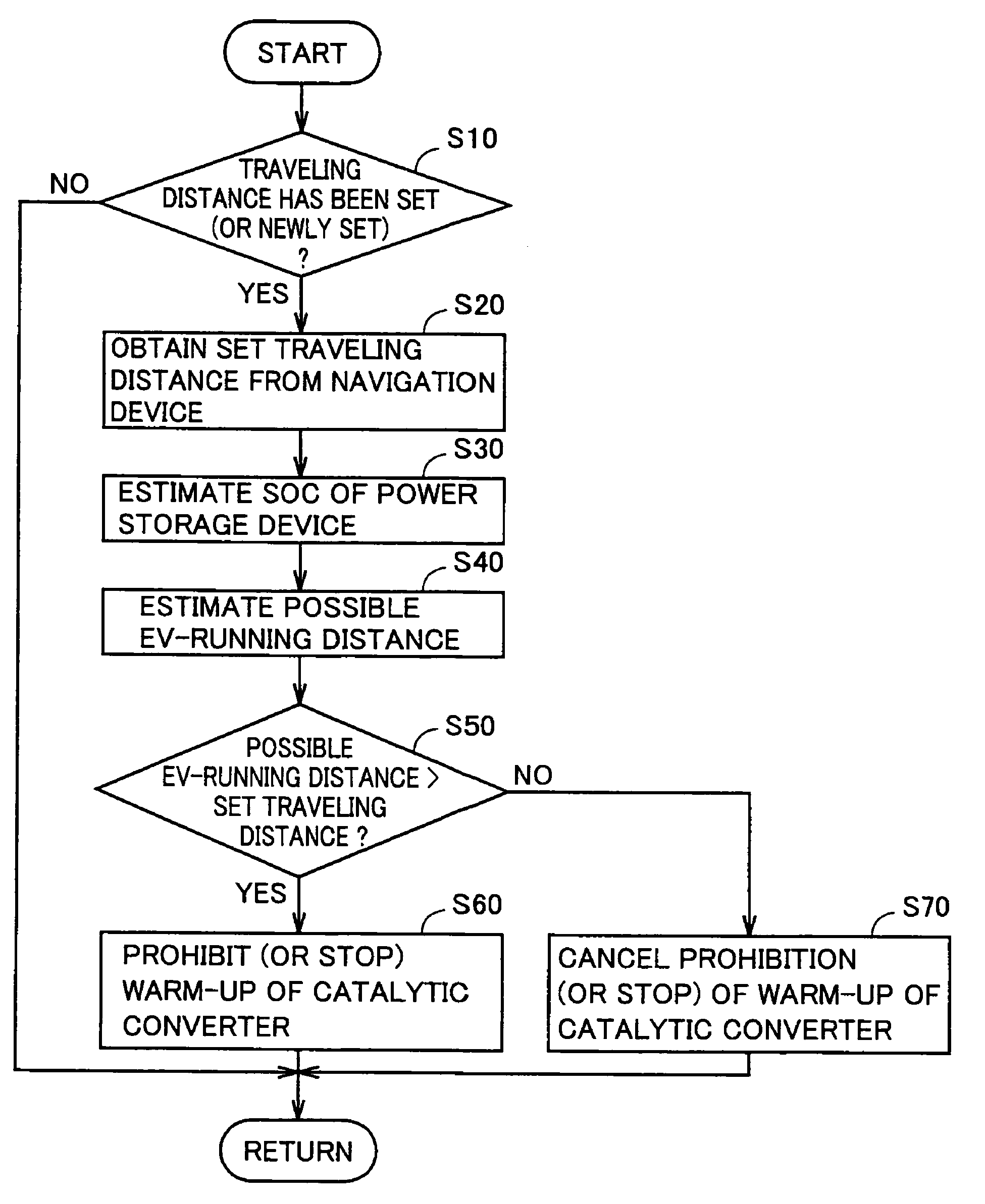
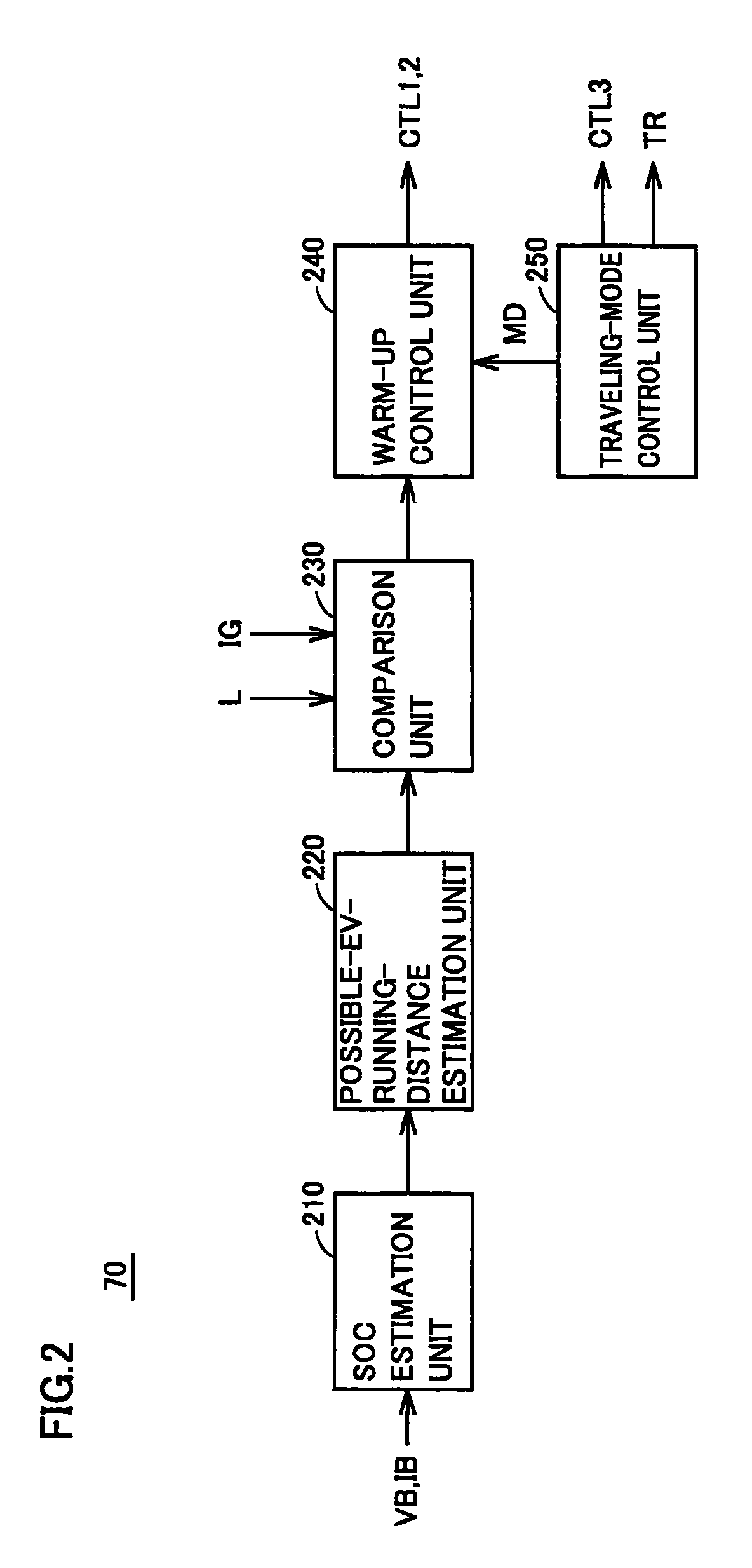
Examples
first embodiment
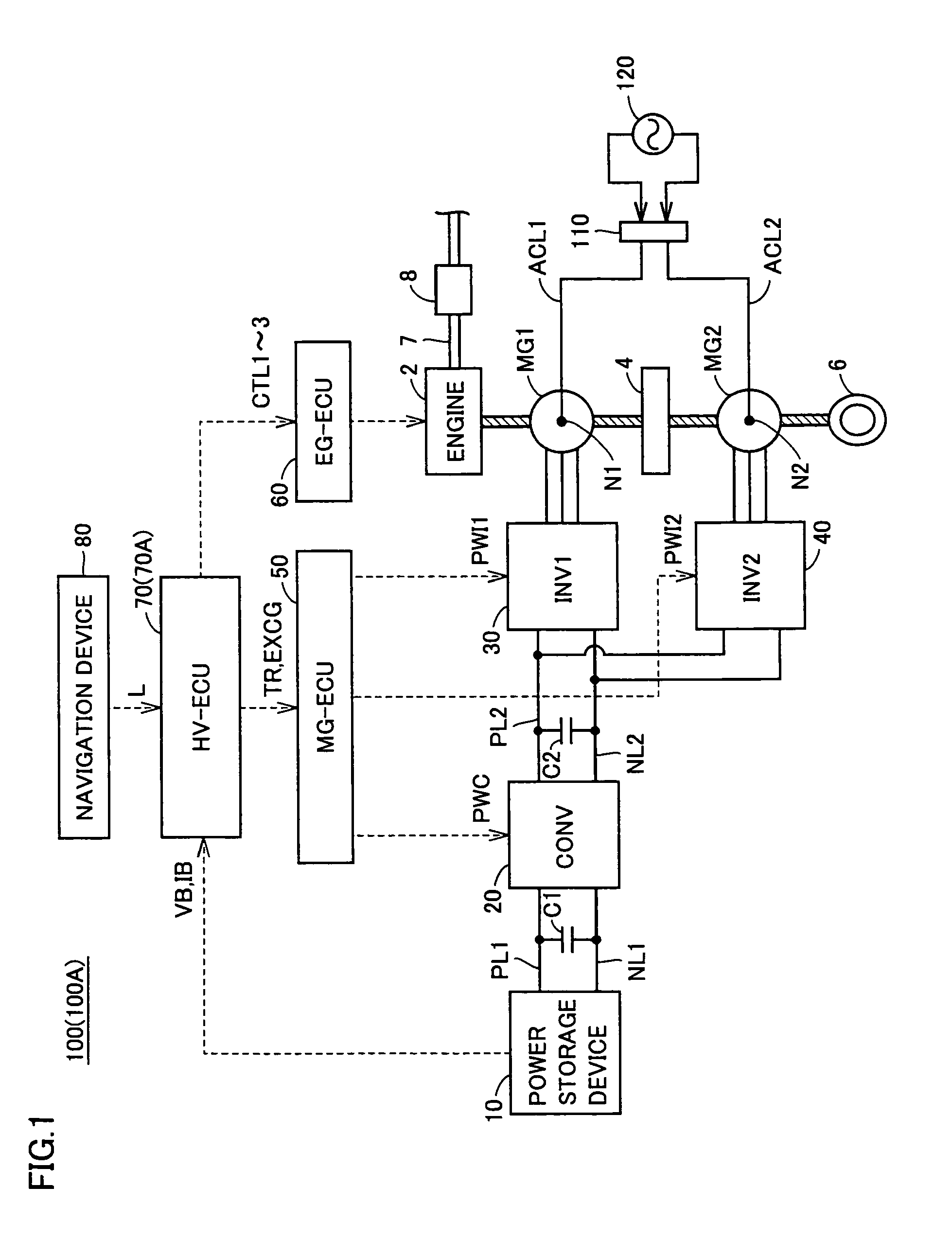
[0035]FIG. 1 is an overall block diagram of a hybrid vehicle according to a first embodiment of the present invention. Referring to FIG. 1, a hybrid vehicle 100 includes an engine 2, an exhaust pipe 7, a catalytic converter 8, motor generators MG1 and MG2, a power split mechanism 4 and a wheel 6. Hybrid vehicle 100 also includes a power storage device 10, a boost converter 20, inverters 30 and 40, positive electrode lines PL1 and PL2, negative electrode lines NL1 and NL2, capacitors C1 and C2, electric power lines ACL1 and ACL2, and a connector 110. Hybrid vehicle 100 further includes an MG-ECU (Electric Control Unit) 50, an EG-ECU 60, an HV-ECU 70 and a navigation device 80.
[0036]This hybrid vehicle 100 runs with engine 2 and motor generator MG2 as power sources. Power split mechanism 4 is coupled to engine 2 and motor generators MG1, MG2 to distribute motive power among them. For example, as power split mechanism 4, a planetary gear mechanism having three rotation shafts of a sun ...
second embodiment
[0077]In a second embodiment, when the possible EV-running distance estimated based on the SOC of power storage device 10 is not longer than set traveling distance L, the SOC in which engine 2 is started (hereinafter also referred to as “engine start SOC”) is set at a value larger than in the case where the possible EV-running distance is longer than traveling distance L. This ensures necessary power for traveling during catalyst warm-up after the engine is started.
[0078]The overall configuration of a hybrid vehicle 100A according to the second embodiment is identical to that of hybrid vehicle 100 shown in FIG. 1 according to the first embodiment.
[0079]FIG. 6 is a functional block diagram of an HV-ECU 70A according to the second embodiment. Referring to FIG. 6, HV-ECU 70A further includes an engine-start-SOC setting unit 260 in addition to the configuration of HV-ECU 70 shown in FIG. 2 according to the first embodiment.
[0080]Engine-start-SOC setting unit 260 sets the above-mentioned...
PUM
 Abstract
Description
Claims
Application Information