Blade air seal with integral barrier

a technology of air sealing and integral barrier, applied in the direction of machines/engines, liquid fuel engines, superimposed coating processes, etc., can solve the problems of relative rotating components of gas turbine engines not being perfectly cylindrical or coaxial with one another, and prone to rub against one another

Active Publication Date: 2014-07-15
RTX CORP
View PDF23 Cites 40 Cited by
  • Summary
  • Abstract
  • Description
  • Claims
  • Application Information

AI Technical Summary

Problems solved by technology

Relatively rotating components of a gas turbine engine are not perfectly cylindrical or coaxial with one another during engine operation.
As a result, the relatively rotating components may occasionally rub against one another.

Method used


Image

  • Blade air seal with integral barrier
  • Blade air seal with integral barrier

Examples


Embodiment Construction

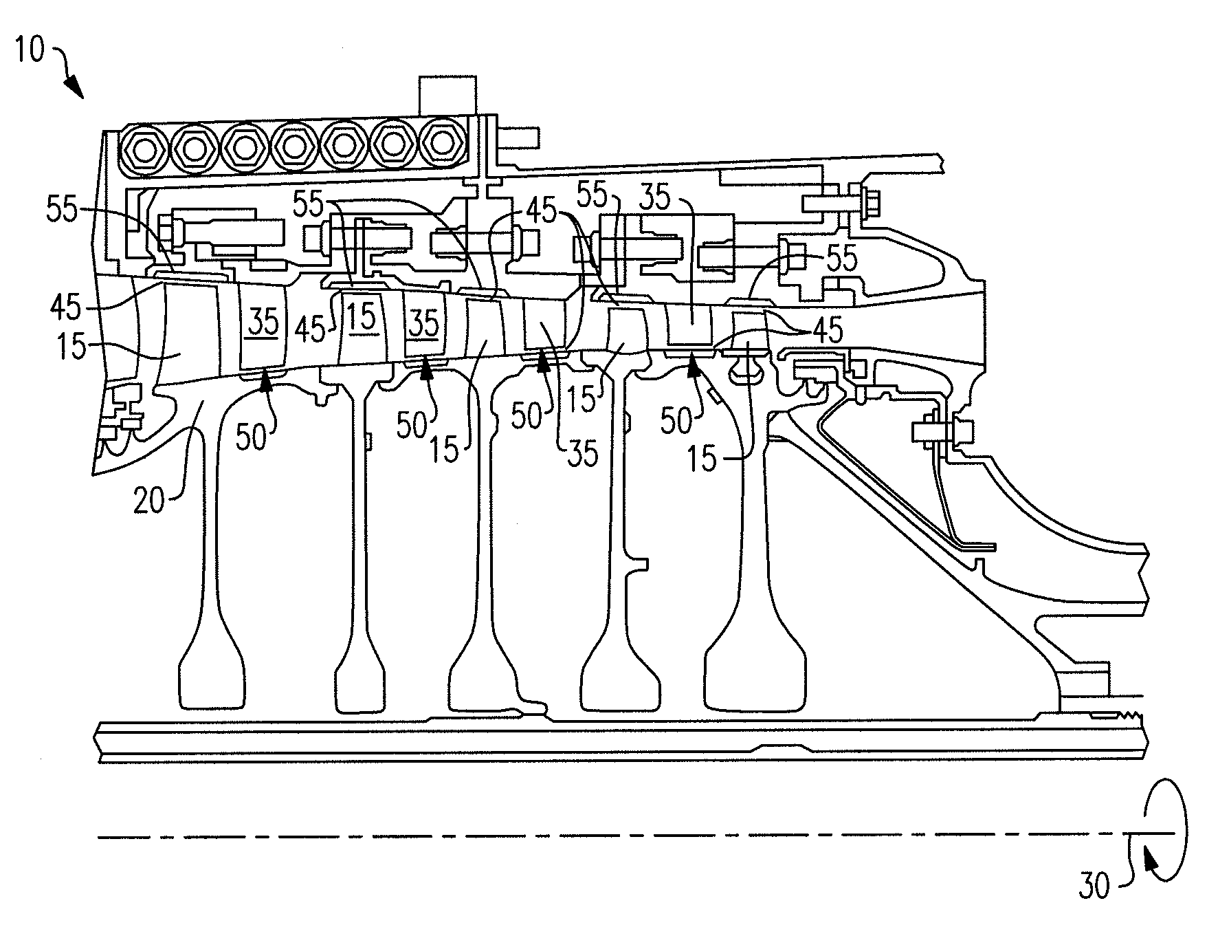
[0021]FIG. 1 shows a portion of a gas turbine engine 10, for example, a high pressure compressor section. The engine 10 has blades 15 that are attached to a hub 20 that rotate about an axis 30. Stationary vanes 35 extend from an outer case 55 (or housing 40), which may be constructed from a nickel alloy, and are circumferentially interspersed between the blades 15, which may be constructed from titanium in one example. A first gap 45 exists between the blades 15 and the outer case 40, and a second gap 50 exists between the vanes 35 and the hub 20.

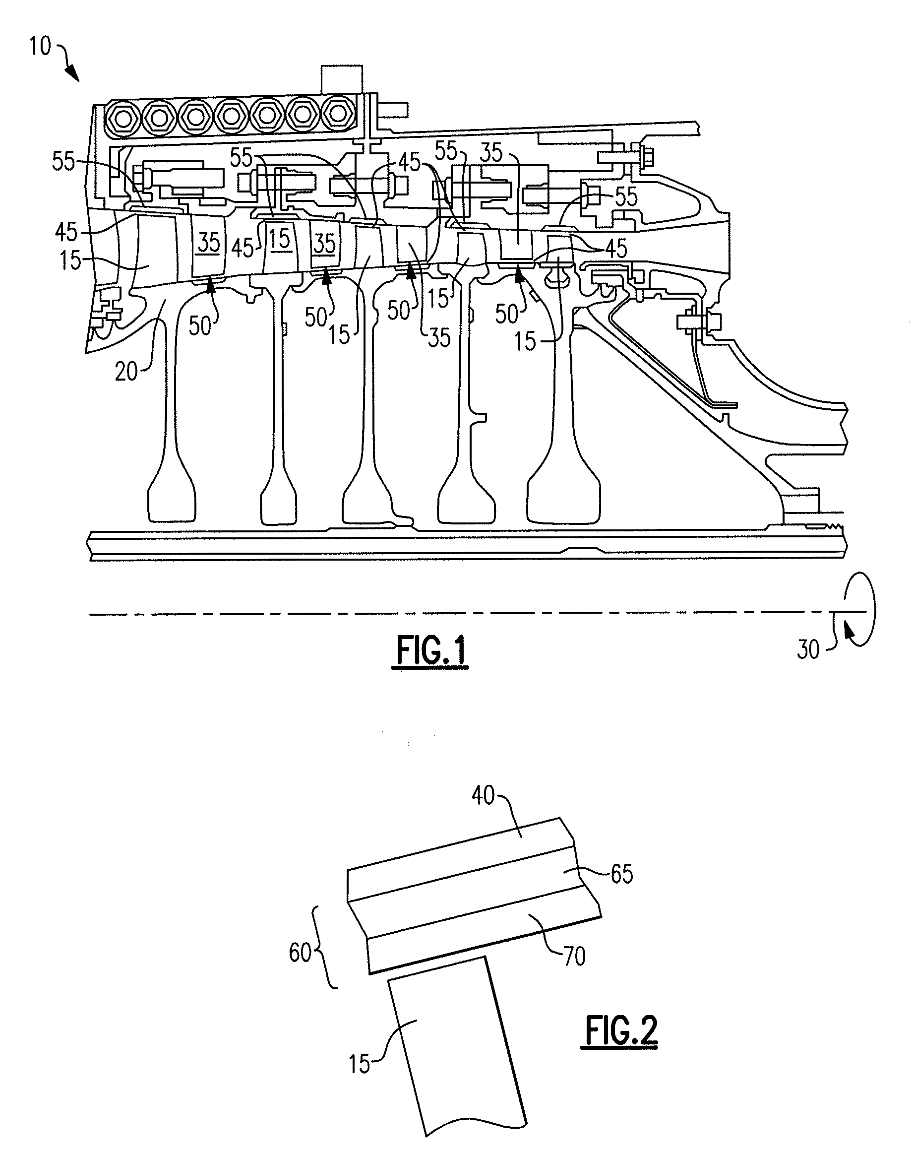
[0022]Air seals 60 (FIG. 2) are positioned in at least one of the first and second gaps 45, 50. Further, the air seals 60 may be positioned on: (a) the outer edge of the blades 15; (b) the inner edge of the vanes 35; (c) an outer surface of the hub 30 opposite the vanes 35; and / or (d) as shown in FIG. 2, on the inner surface of outer case 40 opposite the blades 15. It is desirable that the gaps 45, 50 be minimized and interaction between th...


PUM

PropertyMeasurementUnit
thicknessaaaaaaaaaa
thicknessaaaaaaaaaa
thicknessaaaaaaaaaa

Abstract

An air seal for use with rotating parts includes a thermal barrier coating layer adhered to a substrate. An abradable layer is adhered to the thermal barrier coating layer. The abradable layer comprises a matrix of agglomerated hexagonal boron nitride and a metallic alloy. Another hexagonal boron nitride is interspersed with the matrix.

Description

BACKGROUND OF THE INVENTION[0001]This disclosure relates to an air seal for a gas turbine engine.[0002]In compressor and turbine sections of a gas turbine engine, air seals are used to seal the interface between rotating structure, such as a hub or a blade, and fixed structure, such as a housing or a stator. For example, typically, circumferentially arranged blade seal segments are fastened to a housing, for example, to provide the seal.[0003]Relatively rotating components of a gas turbine engine are not perfectly cylindrical or coaxial with one another during engine operation. As a result, the relatively rotating components may occasionally rub against one another. To this end, an abradable material typically is adhered to the blade seal segments and / or the rotating component.SUMMARY[0004]An embodiment addresses an air seal for use with rotating structure in a gas turbine engine may include: a substrate; a thermal barrier coating layer adhered to the substrate; and an abradable lay...

Claims


Application Information

Patent Timeline
Patent Type & Authority Patents(United States)
IPC IPC(8): F01D11/08
CPCF01D11/122F05D2300/2118F05D2300/2282F05D2300/6032F05D2300/609C23C28/3215C23C28/3455C23C28/347
Inventor STROCK, CHRISTOPHER W.FRELING, MELVIN
Owner RTX CORP
Why Eureka
Try Eureka