Variable hemostasis valve and method of use

a hemostasis valve and variable technology, applied in the field of variable hemostasis valves, can solve the problems of not allowing variable control over the strength of the seal within the hemostasis valve, many hemostasis valves do not fully adapt to large or irregularly sized instruments, and many flaps fail to form a fluid-tight seal around the full structure of the inserted instrument. to achieve the effect of preventing blood loss

Active Publication Date: 2014-07-15
MEDTRONIC INC
View PDF6 Cites 30 Cited by
  • Summary
  • Abstract
  • Description
  • Claims
  • Application Information

AI Technical Summary

Benefits of technology

[0005]The present invention addresses these and other limitations of existing hemostasis valve assemblies by providing a variable hemostasis valve with a controllable seal that is easily opened or closed. The valve may be operated to be in a fully or substantially fully open position prior to percutaneous insertion of a medical instrument, thereby allowing full placement of the instrument into the patient's body with no interference from the hemostasis valve. After the instrument is inserted, the valve may be operated to tighten its seal around the medical instrument. Finally, the valve may be operated to release its seal and return to a fully or substantially fully opened position, enabling the extraction of any inserted medical instruments. Further, the variable hemostasis valve contains a series of locking guides to maintain various rotation positions, thereby allowing the valve seal to maintain an orifice size in a desired open or closed state with a set amount of seal pressure.
[0007]In an embodiment, the variable hemostasis valve is operably coupled to an introducer element, the introducer element being a cylindrical shaft having a removable conical tip coupled thereto. The conical tip or dilator is used to dilate the passage into which the introducer is introduced, while the introducer facilitates the insertion of some medical instrument directly into the patient's body. In use, the variable hemostasis valve is generally positioned outside the patient's body, allowing access to internal systems such as a patient's vascular system through the introducer while preventing blood from escaping. The conical tip functions as a dilator to allow introduction into the bodily space of the cylindrical shaft portion of the introducer. The variable hemostasis valve further provides a user, such as a surgeon, with a variable control seal to engage after insertion of the instrument and to release prior to extraction of the instrument.
[0009]A variable hemostasis valve assembly disclosed according to an embodiment hereof is structured from a valve body having a tubular seal element positioned therein. The valve body includes a proximal housing portion rotatably secured to a distal housing portion. The tubular seal element is positioned such that a passageway thereof forms a midsection of a through lumen of the valve assembly. The tubular seal element has a proximal end operably coupled to the proximal housing portion and a distal end operably coupled to the distal housing portion. The proximal housing portion is further structured to be rotatably received by the distal housing portion, such that the tubular seal element may be rotated to selectively permit fluid flow through the lumen of the valve assembly in an open position or restrict fluid flow through the lumen of the valve assembly in a closed position. Further, the passageway extending through the tubular seal element is structured of a sufficient size and orientation to permit the introduction and extraction of a medical instrument in the open position, and the maintenance of a fluid tight seal around the inserted medical instrument in the closed position.
[0010]A method of use for the variable hemostasis valve according to one embodiment of the present invention may be performed to prevent blood loss while permitting the introduction of intravascular instruments into a patient's body. This method includes first inserting an instrument into the variable hemostasis valve, the lumen of the variable hemostasis valve being defined by a hollow tubular sealing element suspended between and inside two rotatably connected portions of the variable hemostasis valve assembly. Next, the proximal end of the variable hemostasis valve is rotated in a first direction, which causes the tubular element to twist and establish a seal around the instrument. After use of the instrument, the variable hemostasis valve is rotated opposite the first direction, to cause the tubular element to release the seal. Finally, after operation and release of the seal, the instrument may be extracted from the variable hemostasis valve.

Problems solved by technology

Existing hemostasis valves, however, generally do not allow variable control over the strength of the seal within the hemostasis valve.
These flaps often fail to form a fluid-tight seal around the full structure of the inserted instrument, thereby allowing fluids to escape past the valve.
Additionally, many hemostasis valves do not fully adapt to large or irregularly sized instruments.
This results in unintended leakage and bleeding despite the use of the hemostasis valve during medical procedures.

Method used


Image

  • Variable hemostasis valve and method of use
  • Variable hemostasis valve and method of use
  • Variable hemostasis valve and method of use

Examples


Embodiment Construction

[0021]Specific embodiments of the present invention are now described with reference to the figures. The terms “distal” and “proximal” are used in the following description with respect to a position or direction relative to the treating clinician. “Distal” or “distally” are a position distant from or in a direction away from the clinician. “Proximal” and “proximally” are a position near or in a direction toward the clinician.

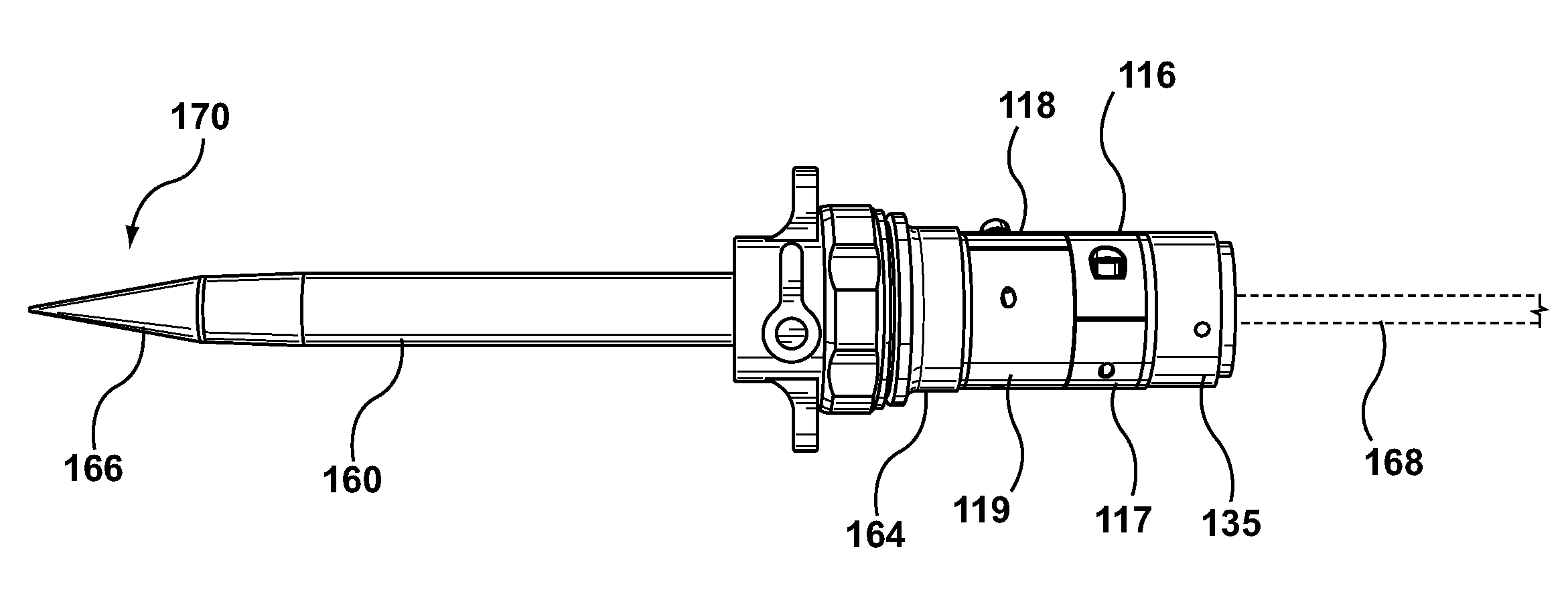
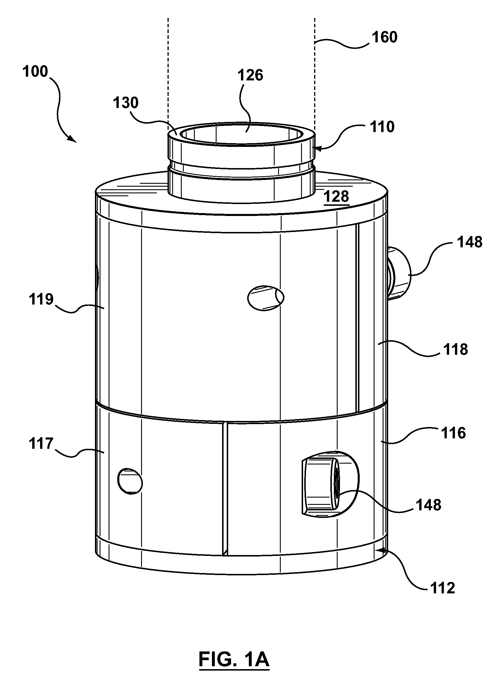
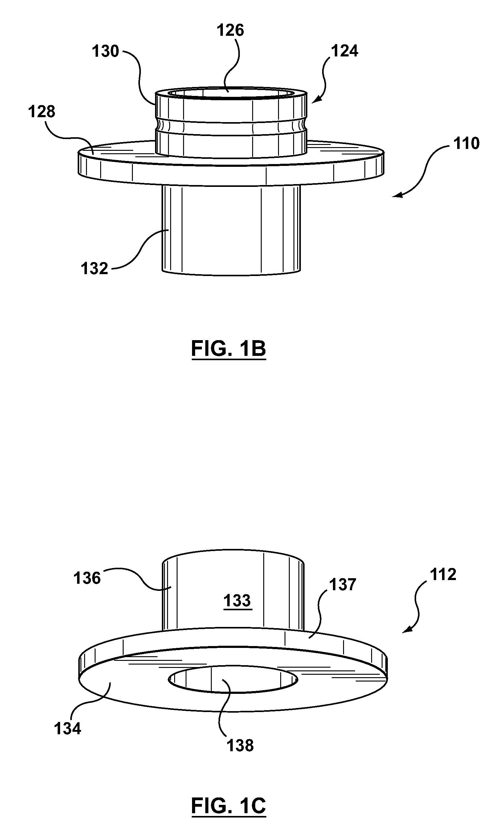
[0022]The presently disclosed variable hemostasis valve apparatus and method of use provide significant advantages over existing hemostasis valves. In addition to providing a fluid-tight seal, the seal is easily tightened and released by an operator through rotation of a proximal portion of the variable hemostasis valve housing. The presently disclosed variable hemostasis valve also provides a flexible, form-adapting seal which can be variably tightened and released upon command. Therefore, the valve may be used in conjunction with a number of insertion assembl...


PUM


Abstract

A variable hemostasis valve is disclosed that may be used during medical procedures to prevent blood loss while permitting the percutaneous introduction, operation, and removal of medical instruments. A flexible tubular seal element is disclosed that is disposed within the variable hemostasis valve to provide a fluid-tight, adjustable seal. After insertion of a medical instrument into the valve through at least a portion of the flexible tubular seal element, a proximal portion of the valve housing may be rotated to cause the tension of the flexible tubular seal element to increase over the inserted medical instrument and engage the valve in a closed position. The proximal portion of the valve housing may then be rotated in an opposite direction to release the seal and return the tubular seal element to a relaxed lumen open position.

Description

CROSS-REFERENCE TO RELATED APPLICATION[0001]This application claims the benefit of U.S. Provisional Application No. 61 / 322,527, filed Apr. 9, 2010, which is incorporated by reference herein in its entirety.FIELD OF THE INVENTION[0002]The present invention is generally directed to a device used in conjunction with percutaneous medical procedures. More particularly, the present invention is directed to a variable hemostasis valve and a method for operating a variable hemostasis valve to enable the reduction of unintended bleeding and fluid leakage during a percutaneous medical procedure.BACKGROUND OF THE INVENTION[0003]Hemostasis valves are well known and used in a variety of percutaneous medical procedures that require the insertion of a catheter or other instruments and devices into a patient's body. For example, hemostasis valves enable the introduction and operation of catheters and other instruments into a patient's cardiovascular system during a minimally invasive interventional...

Claims


Application Information

Patent Timeline
Patent Type & Authority Patents(United States)
IPC IPC(8): A61M1/00A61M5/00A61M5/178
CPCA61M39/0613A61M2039/0626
Inventor MALEWICZ, ANDRZEJ
Owner MEDTRONIC INC
Why Eureka
Try Eureka