Chemical vapor deposition reactor

a chemical vapor and reactor technology, applied in the direction of liquid transfer devices, hose connections, transportation and packaging, etc., can solve the problems of high/inefficient gas and chemical usage, high equipment manufacturing costs, and non-uniform distribution of gas entering flow, so as to reduce the thermal loss of the wafer carrier, provide a thermal barrier to heat loss, and high thermal transfer resistance

Inactive Publication Date: 2014-07-15
VALENCE PROCESS EQUIP
View PDF216 Cites 207 Cited by
  • Summary
  • Abstract
  • Description
  • Claims
  • Application Information

AI Technical Summary

Benefits of technology

[0017]The CVD reactor provides a novel geometry to specific components that function to reduce the gas usage while also improving the performance of the deposition. In one aspect, a number of CVD reactor components with novel geometries are described. In another aspect, new components are described that address the problems of conventional CVD reactors. For example, the chamber top and side wall has a geometry that is significantly different from conventional components. The top and side walls form a flared or curved conical surface. The exit region of the reactor also has an improved geometry that includes a tapered or sloped surface. A novel gas injector is included in one embodiment of the invention to further improve on performance and economy.
[0026]A multi-segment center rotation shaft is provided in one embodiment. The multi-segment shaft has two or more segments that may optionally be used in the reactor. At least one segment of the multi-segment shaft is made from a material having a low thermal conductivity. The multi-segment shaft may have segment interfaces designed to have a high thermal transfer resistance, to reduce thermal losses from the wafer carrier. The multi-segment shaft may generate additional heat near the center of the wafer carrier and provide a thermal barrier to heat losses from the wafter carrier and / or shaft.

Problems solved by technology

The reactor design addresses a number of the problems with existing designs including but not limited to the following: (1) high / inefficient gas and chemicals usage, (2) non-uniform distribution of entering gas flows, (3) high manufacturing costs of equipment, and (4) deposition of problematic byproduct materials on internal reactor surfaces.

Method used


Image

  • Chemical vapor deposition reactor
  • Chemical vapor deposition reactor
  • Chemical vapor deposition reactor

Examples


Embodiment Construction

[0049]The present invention is described in detail using preferred embodiments. The present invention, however, is not limited to these embodiments. Additionally, a requirement in an embodiment is freely applicable to other embodiments, and requirements are mutually replaceable unless special conditions are attached. Specifically, a CVD reactor or MOCVD reactor, and components and parts of the reactors, are described in further detail below. The CVD reactors or MOCVD reactors may comprise other components and parts which are not specifically mentioned herein. Further, it should be understood that the scope of the invention pertains to CVD reactors or MOCVD reactors which may comprise some of the components and parts discussed herein or may comprise all of the components and parts discussed herein.

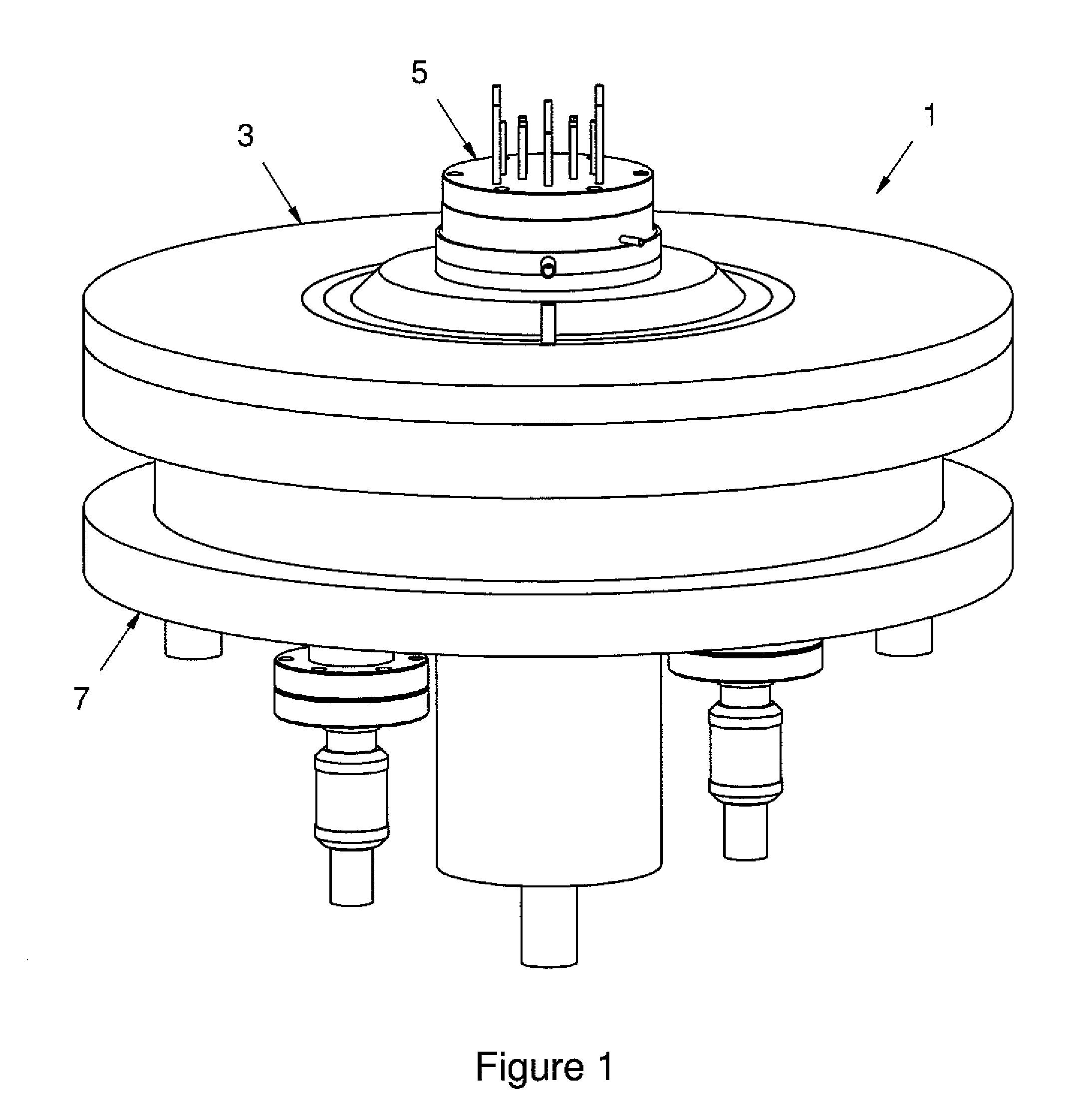
[0050]FIG. 1 illustrates a front perspective view of one embodiment of the entire reactor assembly 1. The entire reactor assembly 1 is comprised of three subassemblies that together form th...


PUM

PropertyMeasurementUnit
thicknessaaaaaaaaaa
temperatureaaaaaaaaaa

Abstract

A CVD reactor, such as a MOCVD reactor conducting metalorganic chemical vapor deposition of epitaxial layers, is provided. The CVD or MOCVD reactor generally comprises a flow flange assembly, adjustable proportional flow injector assembly, a chamber assembly, and a multi-segment center rotation shaft. The reactor provides a novel geometry to specific components that function to reduce the gas usage while also improving the performance of the deposition.

Description

CROSS REFERENCE TO RELATED APPLICATION[0001]This application claims the benefit of U.S. Provisional Patent Application No. 60 / 979,181, filed Oct. 11, 2007, the entirety of which is hereby incorporated by reference into this application.FIELD OF THE INVENTION[0002]The invention pertains to chemical vapor deposition (“CVD”) reactors, including metalorganic chemical vapor deposition (“MOCVD”) reactors.DESCRIPTION OF THE RELATED ART[0003]Chemical vapor deposition (“CVD”) reactors, and in particular metalorganic chemical vapor deposition (“MOCVD”) reactors are used to deposit solid material layers onto a wafer. Such materials typically include compounds of the group III column and group V column elements of the periodic table (referred to as III-V material, but also include “II-VI materials” as well). Materials such as silicon (Si), silicon carbide (SiC), zinc oxide (ZnO) and others are also deposited on wafers or other surfaces using these reactors. Commercially, these reactors are used...

Claims


Application Information

Patent Timeline
Patent Type & Authority Patents(United States)
IPC IPC(8): H01L21/306C23F1/00C23C16/06C23C16/22C23C16/455
CPCC23C16/4584C23C16/4581C23C16/45565C23C16/45574H01L21/67017C23C16/45508Y10T137/9247
Inventor BEGARNEY, MICHAEL J.CAMPANALE, FRANK J.
Owner VALENCE PROCESS EQUIP
Why Eureka
Try Eureka