
Microfluidic device having microvalve

a microfluidic device and micro-valve technology, which is applied in the direction of functional valve types, mechanical equipment, glassware laboratories, etc., can solve the problems of complicated manufacturing process of the microfluidic device, inability to smoothly perform the opening and closing operations of the micro-valve,

Active Publication Date: 2014-07-15
SAMSUNG ELECTRONICS CO LTD
View PDF16 Cites 13 Cited by
  • Summary
  • Abstract
  • Description
  • Claims
  • Application Information

AI Technical Summary

Benefits of technology

The patent describes a way to prevent sticking in a small valve by using a special microstructure on the surface of an elastic film. This helps to improve the operation of the valve and ensure it works correctly.

Problems solved by technology

However, in the case of a conventional microvalve, normally, the elastic film and the valve seat contact each other when the microvalve is not in operation.
In this case, the opening and closing operations of the microvalve may not be smoothly performed when the microvalve is finally operated.
In order to prevent stiction or sticking between the elastic film and the valve sheet when the microvalve is finally operated, the manufacturing process of the microfluidic device may be complicated.

Method used


Image

  • Microfluidic device having microvalve
  • Microfluidic device having microvalve
  • Microfluidic device having microvalve

Examples


Embodiment Construction

[0046]Reference will now be made in detail to embodiments, examples of which are illustrated in the accompanying drawings, wherein like reference numerals refer to like elements throughout. This invention may, however, be embodied in many different forms and should not be construed as limited to the exemplary embodiments set forth herein. Rather, these embodiments are provided so that this disclosure will be thorough and complete, and will fully convey the scope of the invention to those skilled in the art. In the drawings, the thicknesses of layers and regions are exaggerated for clarity.

[0047]It will be understood that when an element or layer is referred to as being “on” or “connected to” another element or layer, the element or layer can be directly on or connected to another element or layer or intervening elements or layers. In contrast, when an element is referred to as being “directly on” or “directly connected to” another element or layer, there are no intervening elements ...


PUM


Abstract

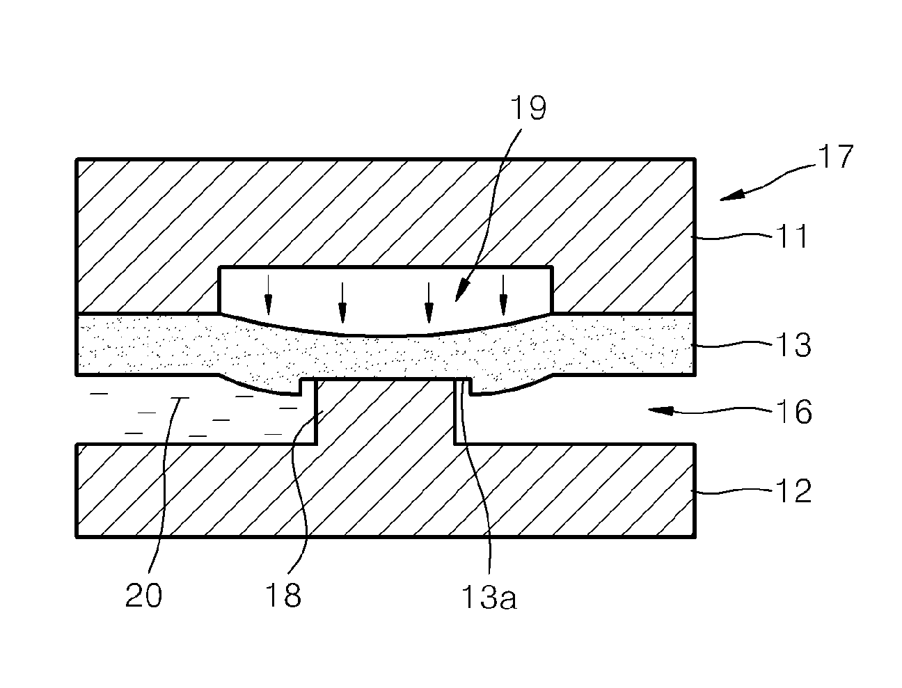
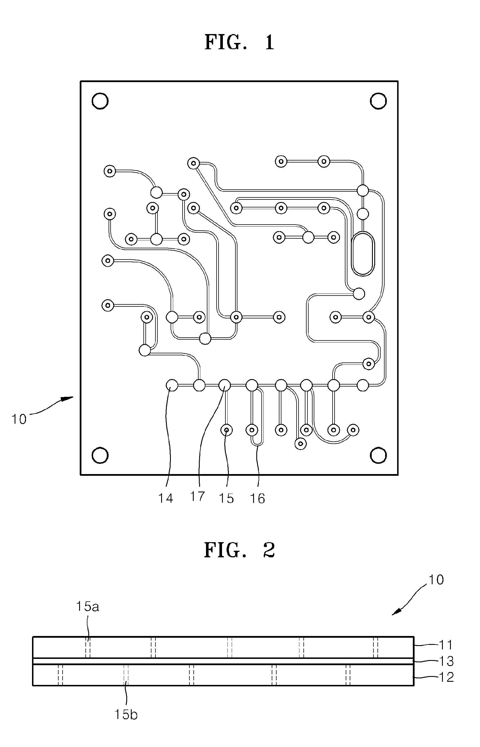
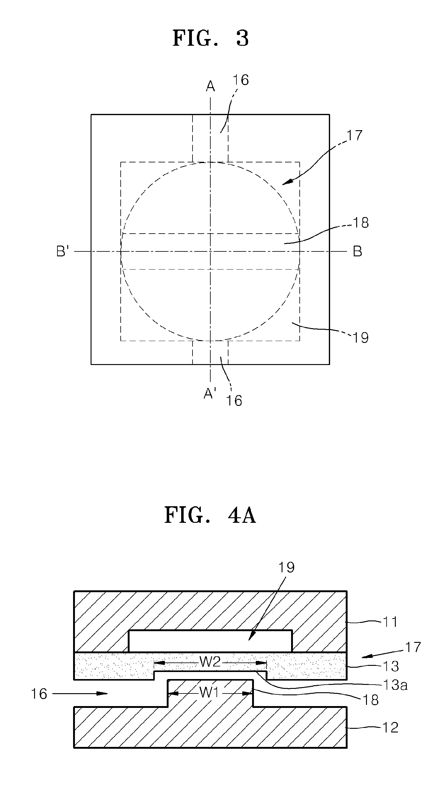
A microfluidic device including a microvalve includes a first substrate, a second substrate facing the first substrate, an elastic film between the first and second substrates, a microfluidic channel on the second substrate, a valve seat of the second substrate protruding in the microfluidic channel, and a fine structure on a surface of the elastic film, facing the valve seat and which contacts the valve seat when the microvalve is operated.

Description

CROSS-REFERENCE TO RELATED APPLICATIONS[0001]This application claims priority to Korean Patent Application No. 10-2010-0056758, filed on Jun. 15, 2010, and all the benefits accruing therefrom under 35 U.S.C. §119, the disclosure of which is incorporated herein in its entirety by reference.BACKGROUND[0002]1. Field[0003]Provided are microfluidic devices having a microvalve, and more particularly, microfluidic devices including microstructures on a surface of an elastic film in a microvalve.[0004]2. Description of the Related Art[0005]An analysis of samples related to clinics or the environment is achieved through a biochemical, chemical, or mechanical treatment process. Recently, the development of techniques for diagnosing or monitoring a biological sample has drawn a significant interest. The application of a molecular diagnosis method based on nucleic acid has significantly increased recently in the fields of diagnosing an infectious disease or cancer, pharmacogenomics, or developi...

Claims


Application Information

Patent Timeline
Patent Type & Authority Patents(United States)
IPC IPC(8): F16K1/00B01L99/00F16K99/00
CPCF16K99/0026B01L3/502738B01L2300/123B01L2400/0481B01L2400/0655F16K99/0015F16K99/0059F16K2099/008F16K2099/0084
Inventor JUNG, WON-JONGPARK, CHIN-SUNGNAMKOONG, KAKKIM, JOON-HOYEO, HYUNG-SOK
Owner SAMSUNG ELECTRONICS CO LTD
Learn More