
Printing blanket including a non-extensible backing layer and a relief area which may be mounted in a variety of lockup mechanisms

a technology of non-extensible backing and relief area, which is applied in the field of printing blankets, can solve the problems of difficult mounting and tensioning of blankets containing metal backings on blanket cylinders, high manufacturing cost of metal backed blankets, and difficult mounting of blankets around small diameter printing cylinders. achieve the effect of minimizing the width of the non-print gap

Inactive Publication Date: 2014-07-22
DAY INT INC
View PDF37 Cites 2 Cited by
  • Summary
  • Abstract
  • Description
  • Claims
  • Application Information

AI Technical Summary

Benefits of technology

The non-extensible polymeric backing layer with relief areas enables easy mounting in various printing presses, maintains high print quality, and reduces manufacturing costs, while minimizing the need for frequent retensioning and reducing non-print gap width.

Problems solved by technology

However, blankets containing a metal backing are difficult to mount and tension properly on a blanket cylinder which uses more conventional mounting mechanisms such as single or dual reel rods or “t-bar” type lockups.
This is due to the metal at the leading and trailing ends of the blanket which is relatively inflexible and difficult to feed into the cylinder gap.
In addition, the stiffness of the metal-backed blankets makes it difficult to mount the blankets around small diameter printing cylinders.
Further, metal backed blankets are expensive to manufacture due to the complex processes required to assemble and finish the blankets to the precise dimensions and specifications required in printing processes.

Method used


Image

  • Printing blanket including a non-extensible backing layer and a relief area which may be mounted in a variety of lockup mechanisms
  • Printing blanket including a non-extensible backing layer and a relief area which may be mounted in a variety of lockup mechanisms
  • Printing blanket including a non-extensible backing layer and a relief area which may be mounted in a variety of lockup mechanisms

Examples


Embodiment Construction

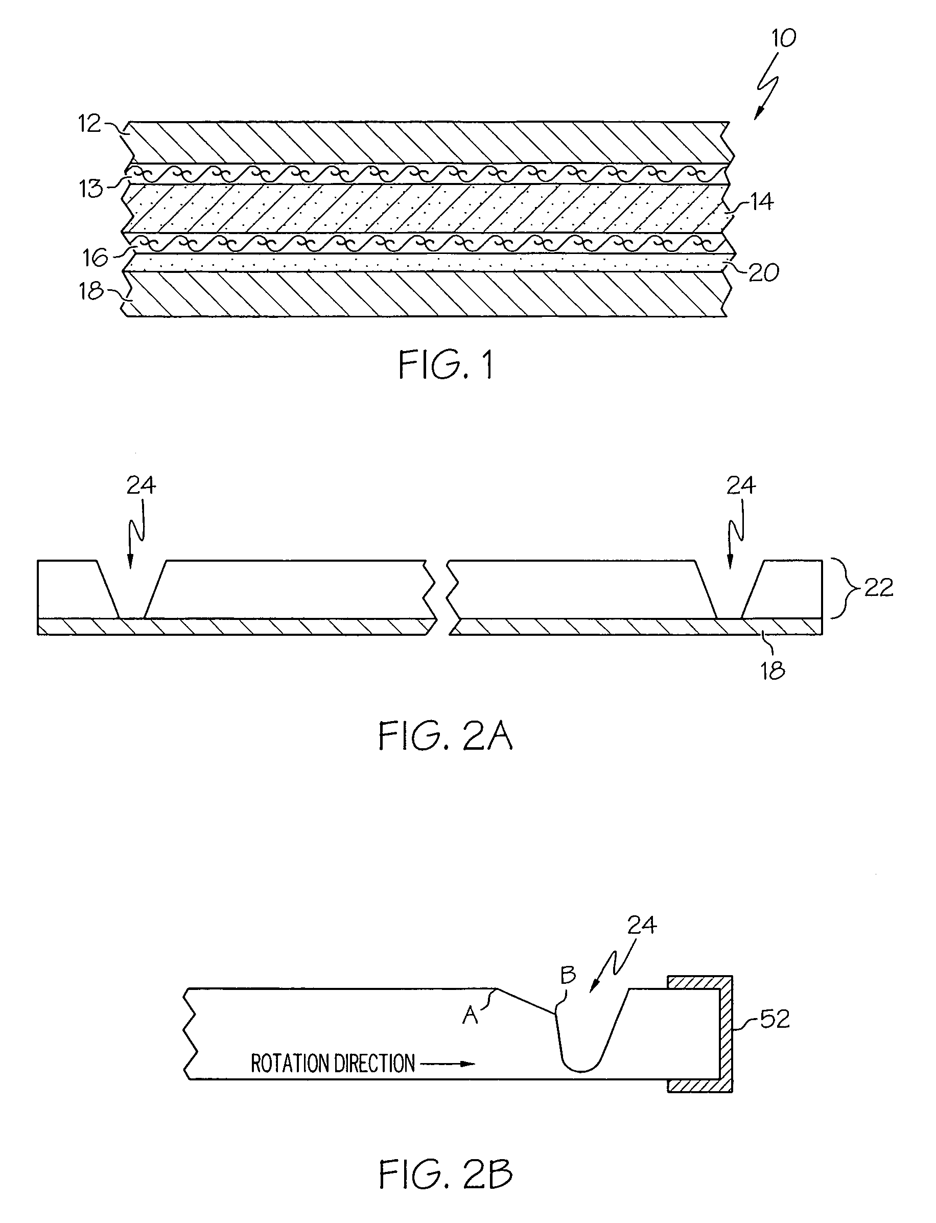
[0031]The printing blanket of the present invention including a non-extensible backing layer provides a number of advantages over prior metal or fabric backed blankets. Because the backing is comprised of a non-extensible material, it provides better print quality and printing efficiency over its operating life as it eliminates stretching and / or retensioning of the printing blanket during mounting and operation. And, by utilizing a polymeric material as a backing material, the printing blanket is less expensive to manufacture than blankets utilizing metal backings.

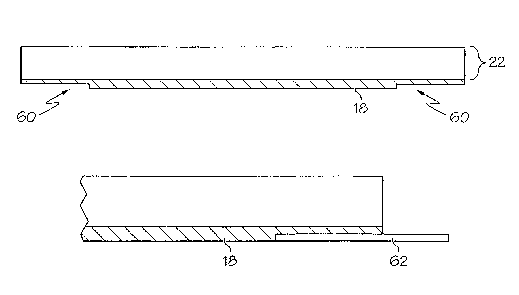
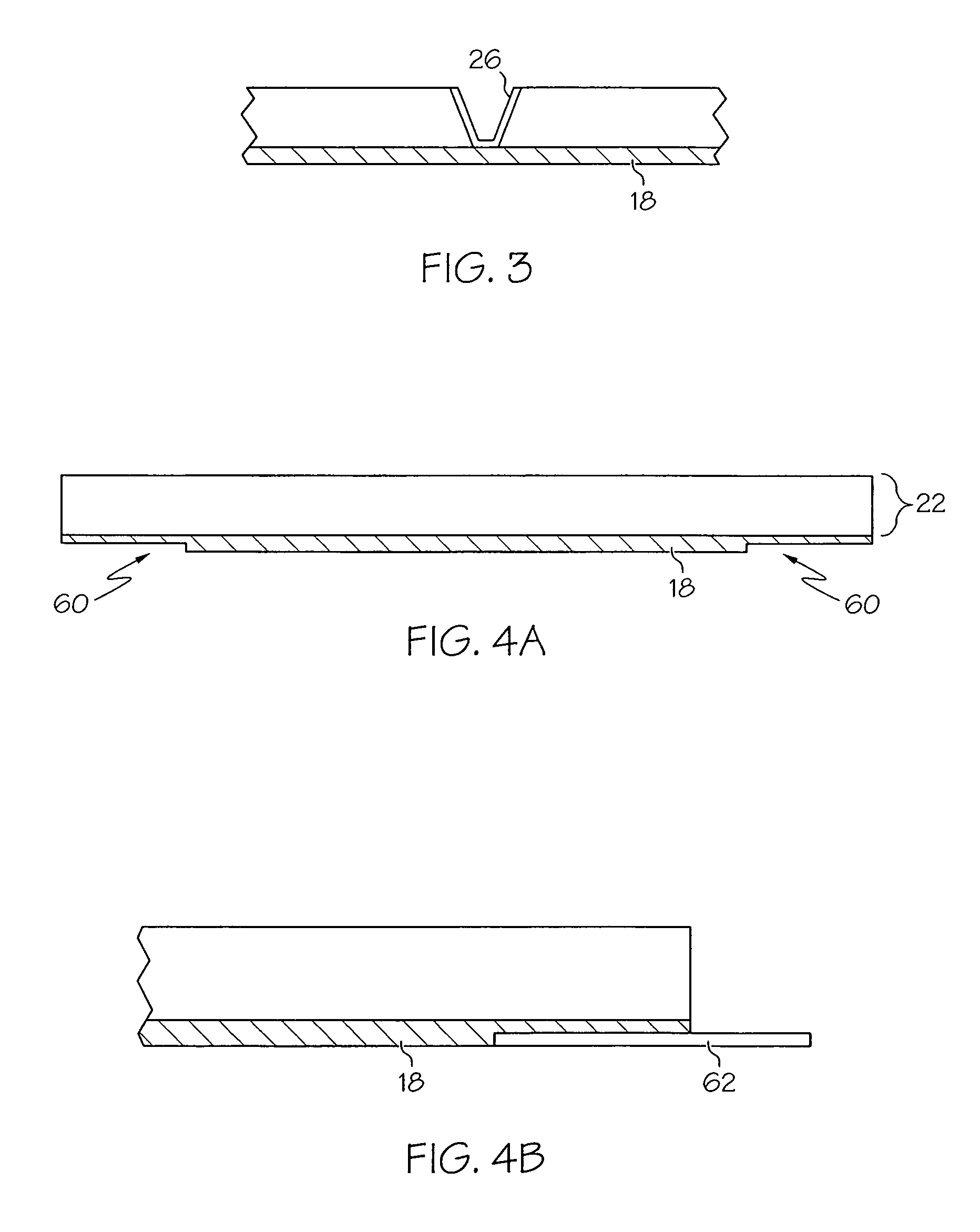
[0032]In addition, the blanket of the present invention is significantly easier to mount in standard press lockups than blankets utilizing metal backings. By providing the printing blanket of the present invention with relief areas at each end, the blanket may be used in substantially all conventional types of lockup mechanisms without requiring any modifications to the mechanisms or the use of any special lockup procedure...


PUM


Abstract

A printing blanket is provided which may include a printable surface ply, a compressible ply, one or more reinforcing fabric plies, and a non-extensible backing layer comprising a polymeric material. The printing blanket has first and seconds ends which are adapted to be inserted into the gap of a printing blanket cylinder, where each of the first and second ends may include a relief area formed by removing or molding a portion of the blanket or by removing or molding a portion of the non-extensible backing layer such that the blanket may be mounted in a wide variety of printing presses using a number of different lock-up mechanisms.

Description

CROSS REFERENCE TO RELATED APPLICATIONS[0001]This application claims the benefit of U.S. Provisional Application No. 60 / 734,872 entitled PRINTING BLANKET HAVING A NON-EXTENSIBLE BACKING filed Nov. 9, 2005. The entire contents of said application are hereby incorporated by reference.BACKGROUND OF THE INVENTION[0002]The present invention relates to a printing blanket having a non-extensible backing layer and including at least one relief area, and more particularly, to a printing blanket which may be mounted in a wide variety of printing presses using a number of different lockup mechanisms.[0003]One of the most common commercial printing processes is offset lithography. In this printing process, ink is offset from a printing plate to a rubber-surfaced printing blanket mounted on a blanket cylinder before being transferred to a substrate, such as paper. Typically, the blanket cylinder comprises a chrome or nickel-plated steel cylinder having a longitudinal opening or “gap” therein. An...

Claims


Application Information

Patent Timeline
Patent Type & Authority Patents(United States)
IPC IPC(8): B41F27/12B41F27/10B41F21/00
CPCB41F13/10B41F27/10B41F27/12B41N10/06
Inventor CZERNER, RICHARD, L.
Owner DAY INT INC
Learn More