Device for controlling variable-pitch blades in a turbomachine compressor

a turbomachine and variable-pitch technology, which is applied in the direction of rotors, marine propulsion, vessel construction, etc., can solve the problems of loss of precision in variable-pitch blade control, variation in relative positioning of the cylinder and the control shaft,

Active Publication Date: 2014-07-22
SN DETUDE & DE CONSTR DE MOTEURS DAVIATION S N E C M A
View PDF7 Cites 22 Cited by
  • Summary
  • Abstract
  • Description
  • Claims
  • Application Information

AI Technical Summary

Benefits of technology

[0011]The second blade foot is advantageously engaged in an eccentric guide ring housed in the orifice of the second tab to compensate for any misalignment between the orifices of the two attachment tabs. Two radially grooved washers are preferably engaged on the eccentric ring and inserted between the second tab and an external annular rim of the ring, one of the washers ...

Problems solved by technology

The production and assembly tolerances of these parts mean that the relative positioning of the cylinder an...

Method used


Image

  • Device for controlling variable-pitch blades in a turbomachine compressor
  • Device for controlling variable-pitch blades in a turbomachine compressor
  • Device for controlling variable-pitch blades in a turbomachine compressor

Examples


Embodiment Construction

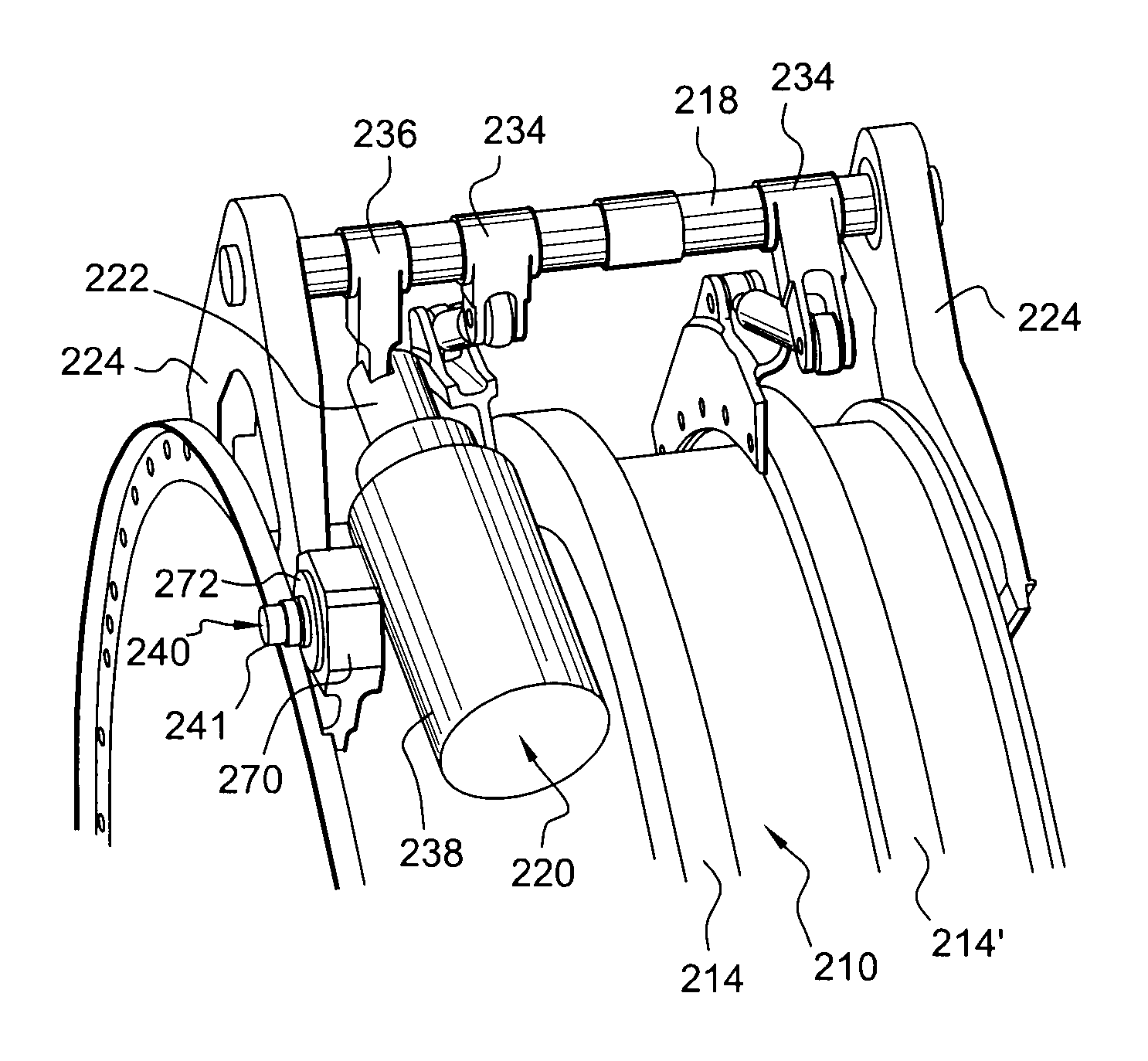
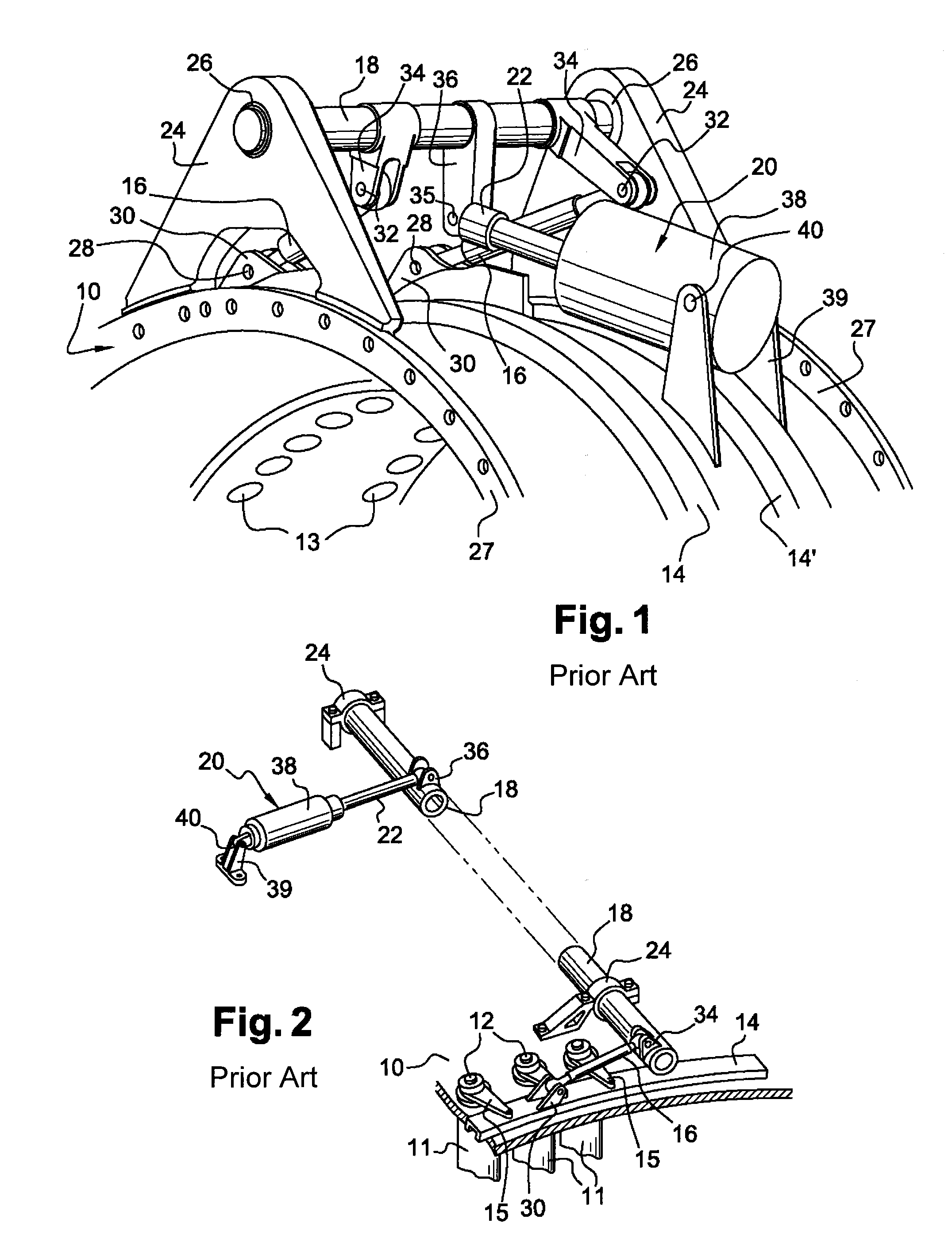
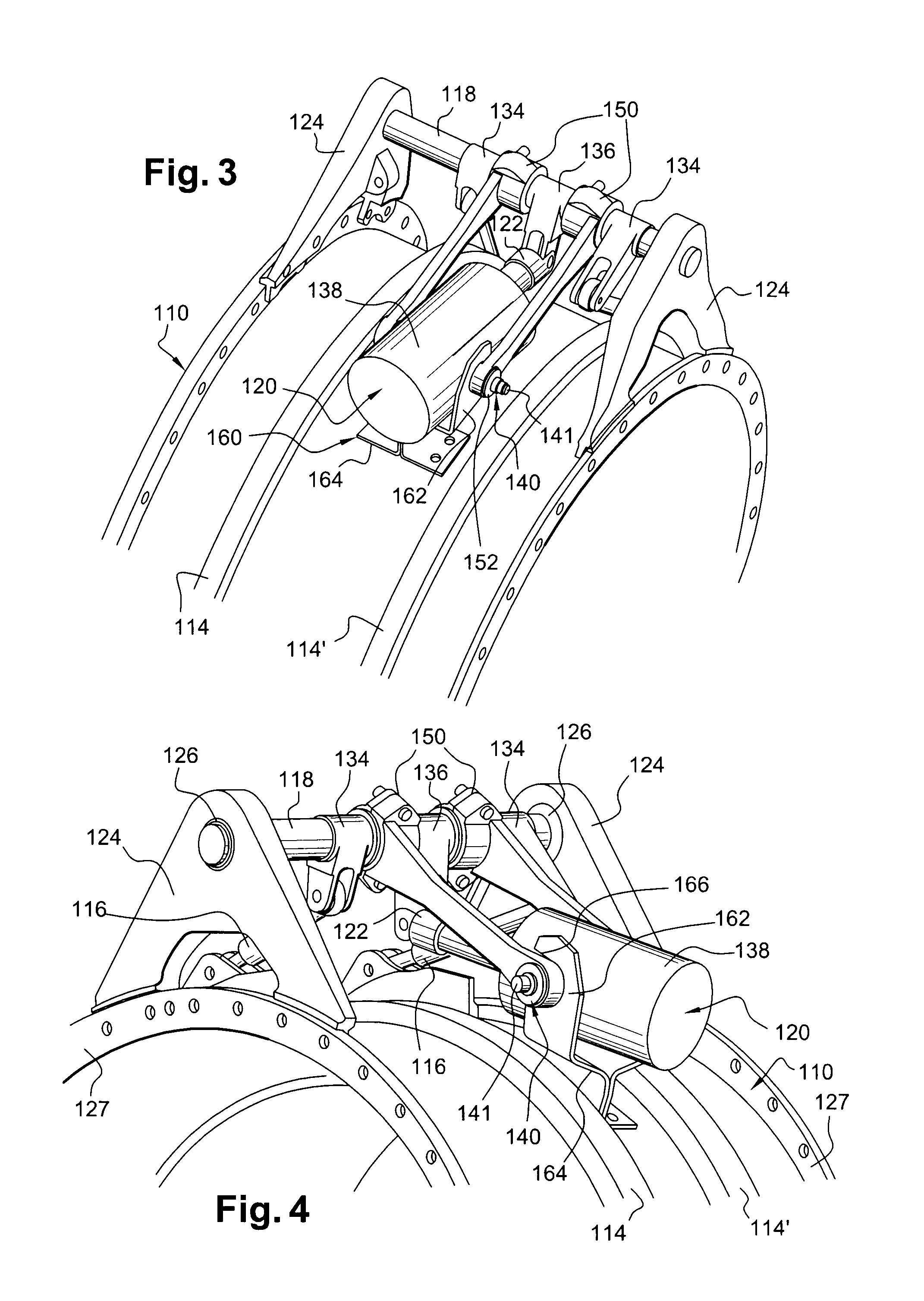
[0027]The devices for controlling variable-pitch blades represented in FIGS. 1 and 2 are each mounted on a substantially cylindrical external casing 10 of a turbomachine compressor such as an aircraft turbojet or turboprop.

[0028]The casing 10 bears one or a plurality of variable-pitch blade stages, one of which is partially represented in FIG. 2. The blades 11 of a stage are evenly distributed about the axis of revolution of the casing 10, and each comprise a vane connected at the radially external end thereof to a radial cylindrical pivot 12 running along the axis of rotation of the blade and which is engaged in a cylindrical duct 13 of the casing. The radially external end of said pivot is connected to one end of a connecting rod 15 wherein the other end is connected to a control ring 14, 14′.

[0029]The control device may comprise one or a plurality of rings 14, 14′. It comprises two thereof in the example in FIG. 1 and only one in the case of FIG. 2. Each ring 14, 14′ encompasses ...


PUM


Abstract

A device for controlling variable-pitch blades in a turbomachine compressor, including at least one control ring surrounding an external casing of the compressor, and a control shaft connected to the ring and to the rod of an actuator, the body of which is mounted such that it can pivot about an axle borne by a support mechanism of the control shaft so as to guarantee a precise relative positioning of the axis of pivoting of the actuator with respect to the control shaft.

Description

BACKGROUND[0001]The present invention relates to a device for controlling variable-pitch blades in a turbomachine such as an aircraft turbojet or turboprop.[0002]A turbomachine of this type comprises one or a plurality of variable-pitch guide blade stages which are mounted between the wheels of a compressor. These variable-pitch blades are carried by the turbomachine stator and are adjustable in position about the axes thereof to optimise gas flow in the turbomachine engine.[0003]Each variable-pitch blade comprises a cylindrical pivot at each of the ends thereof, said pivots defining the axis of rotation of the blade. The radially external pivot is engaged in a cylindrical duct of an external annular casing of the turbomachine and is connected by a connecting rod to a ring which is mounted about the casing and is in turn connected by a lever to a control shaft actuated by a cylinder. The control shaft runs parallel to the casing axis and may be connected to one or a plurality of the...

Claims


Application Information

Patent Timeline
IPC IPC(8): F01D17/16
CPCF04D29/563
Inventor BOURU, MICHEL, ANDRE
Owner SN DETUDE & DE CONSTR DE MOTEURS DAVIATION S N E C M A
Why Eureka
Try Eureka