Vehicle drive system

a technology of drive system and drive shaft, which is applied in the direction of engine-driven generator propulsion, transportation and packaging, and gearing, etc., can solve the problems of difficult complicated drive system construction, and inability to reduce the size of the drive system, so as to reduce the loss of gear engagement

Active Publication Date: 2014-07-22
TOYOTA JIDOSHA KK
View PDF46 Cites 29 Cited by
  • Summary
  • Abstract
  • Description
  • Claims
  • Application Information

AI Technical Summary

Benefits of technology

[0007]The present invention provides a drive system operable to place a transmission mechanism in a direct-drive gear position by connecting an internal combustion engine with an output member without involving any change gear train therebetween, thereby to reduce losses due to engagement of gears.

Problems solved by technology

Therefore, the drive system inevitably suffers from losses due to engagement of the gears during transmission of power of the engine.
Also, it is difficult to reduce the size of the drive system since the electric motor is disposed between the two clutch shafts.
Furthermore, the rotor shaft of the motor and each of the clutch shafts, which are perpendicular to each other, are connected to each other via bevel gears, and this arrangement makes the drive system complicated in construction.

Method used


Image

  • Vehicle drive system
  • Vehicle drive system
  • Vehicle drive system

Examples


first embodiment

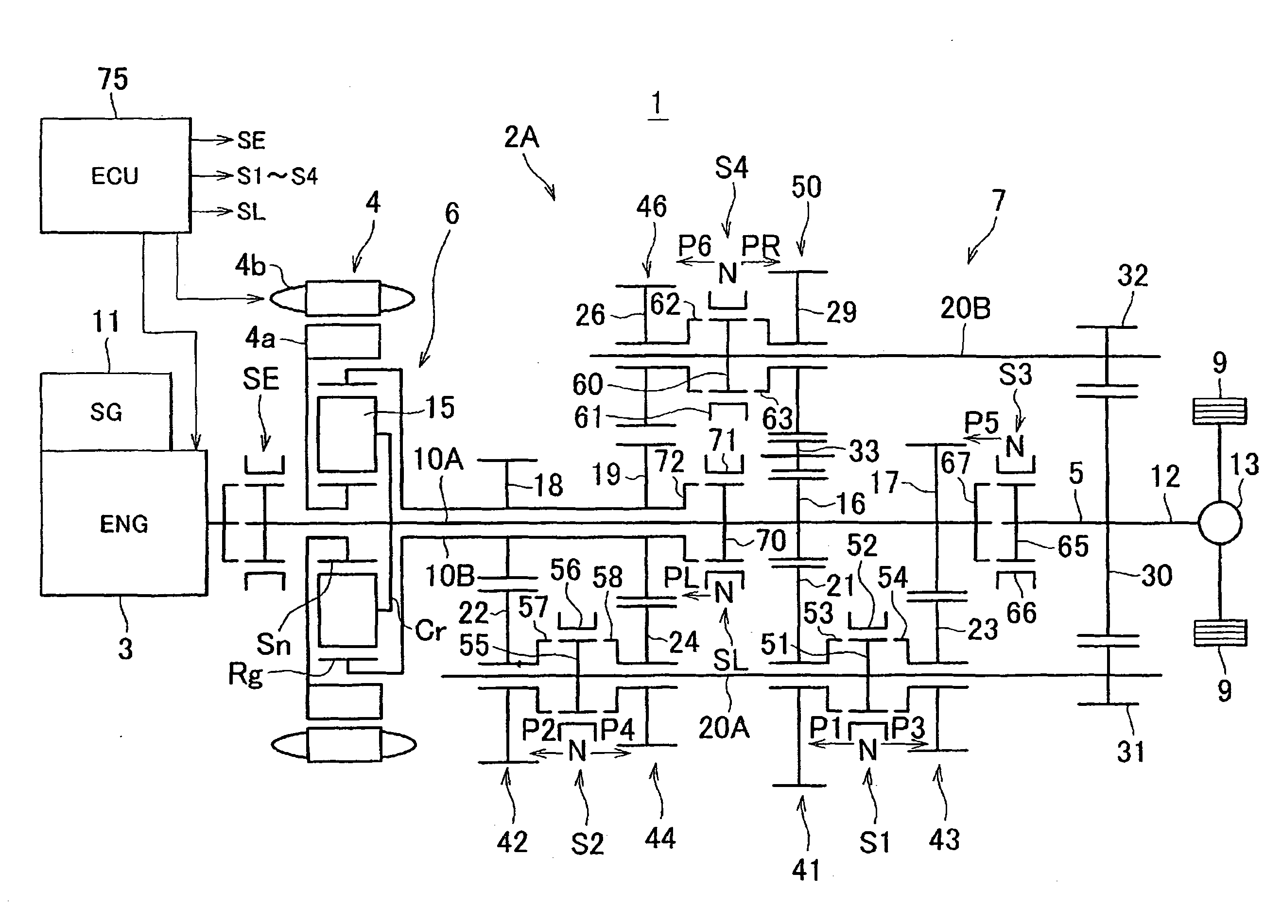
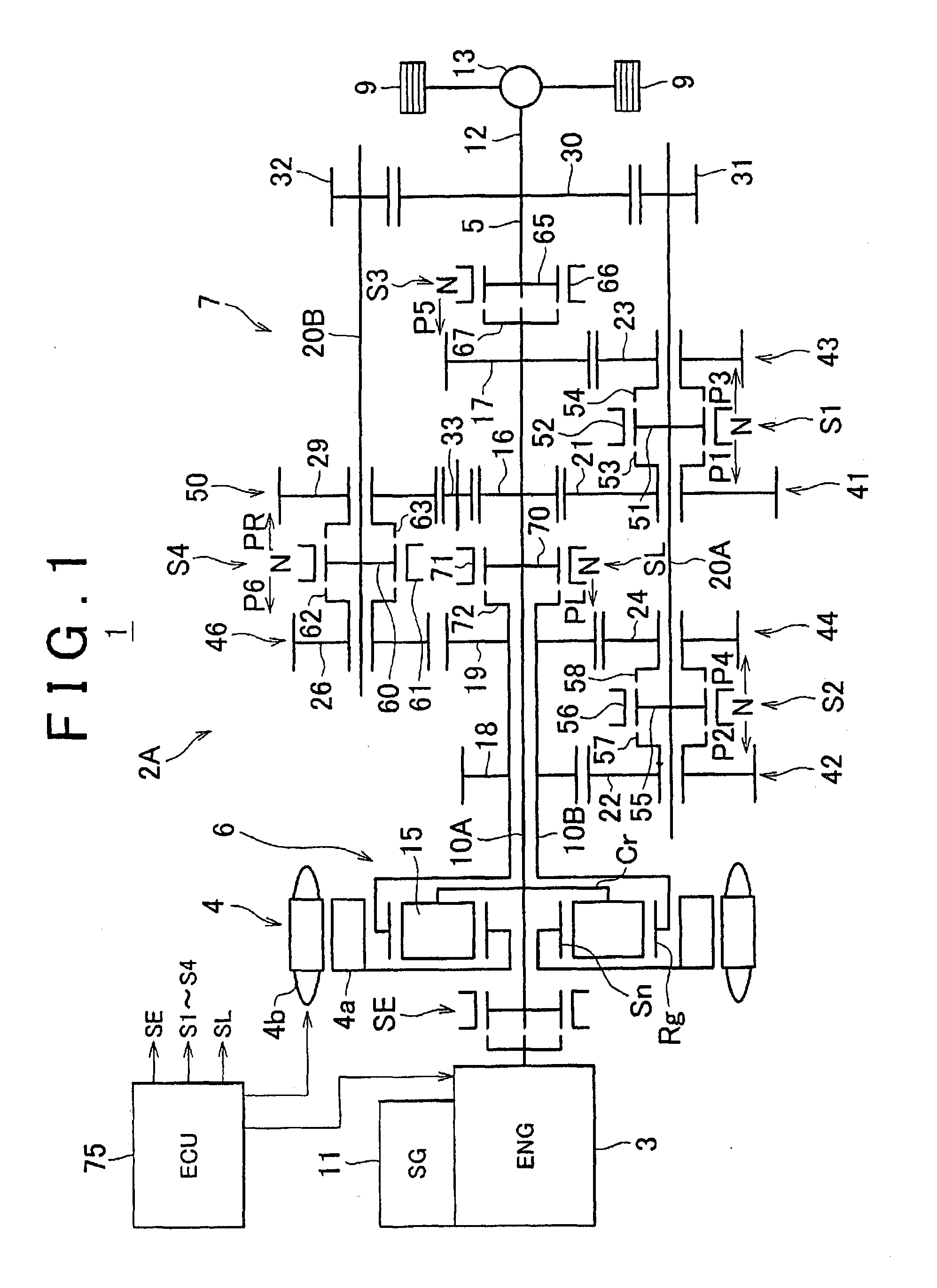
[0046]FIG. 1 schematically illustrates a vehicle in which a drive system according to the invention is employed. As shown in FIG. 1, the vehicle 1 is a so-called hybrid vehicle having a FR (front-engine rear-drive) type layout. The vehicle 1 is provided with a drive system 2A for running the vehicle. The drive system 2A includes an internal combustion engine 3, a motor-generator (MG) 4 as an electric motor, an output shaft 5 as an output member that delivers power to driving wheels 9 of the vehicle 1, a power distribution mechanism 6 as a differential mechanism to which the engine 3 and the MG4 are coupled, and a transmission mechanism 7 that changes the speed of the output of the power distribution mechanism 6 and transmits the resulting power output to the output shaft 5. The rotation of the output shaft 5 is transmitted to the left and right driving wheels 9, respectively, via a propeller shaft 12 and a differential gear 13. The propeller shaft 12 is coupled to the output shaft 5...

second embodiment

[0086]Suitable combinations of the gears mounted on the driveshafts 10A, 10B and the countershafts 20A, 20B engage with each other so as to provide a plurality of change gear trains having different gear ratios. In the second embodiment, the change gear trains are constructed as follows. A change gear train 41 that provides the first-speed gear position consists of the gears 16, 21 provided between the first driveshaft 10 and the first countershaft 20A, and a change gear train 42 that provides the second-speed gear position consists of the gears 18, 22 provided between the second driveshaft 10B and the first countershaft 20A, while a change gear train 43 that provides the third-speed gear position consists of the gears 17, 23 provided between the first driveshaft 10A and the first countershaft 20A, and a change gear train 44 that provides the fourth-speed gear position consists of the gears 19, 24 provided between the second driveshaft 10B and the first countershaft 20A. A change ge...


PUM


Abstract

A drive system includes a transmission mechanism that establishes a plurality of gear positions comprising a first-speed through sixth-speed gear positions and a reverse-drive gear position, by switching among change gear trains and coupling a first driveshaft to an output member, and also includes a lock clutch that switches a power distribution mechanism between a locked state in which a ring gear and a carrier are coupled to each other and are inhibited from rotating in a differential fashion, and a released state in which the inhibition of the differential rotation is cancelled.

Description

[0001]The disclosure of Japanese Patent Application No. 2008-145669 filed on Jun. 3, 2008, including the specification, drawings and abstract is incorporated herein by reference in its entirety.BACKGROUND OF THE INVENTION[0002]1. Field of the Invention[0003]The invention relates to a vehicle drive system in which an internal combustion engine and an electric motor are provided as driving sources.[0004]2. Description of the Related Art[0005]In a conventional vehicle drive system (as disclosed in Japanese Patent Application Publication No. 2002-204504 (JP-A-2002-204504)), a twin-clutch type transmission using a plurality of gears is coupled to an internal combustion engine, and an electric motor is disposed between two clutch shafts of the transmission, such that a rotor shaft of the motor extends in a direction perpendicular to the clutch shafts. One of the clutch shafts is connected to the rotor shaft of the motor via a pair of bevel gears, and the other clutch shaft is connected to...

Claims


Application Information

Patent Timeline
Patent Type & Authority Patents(United States)
IPC IPC(8): F16H3/72B60K6/26B60K6/36B60K6/365B60K6/40B60K6/48B60K6/547B60L11/14F16H3/097F16H37/06F16H59/44F16H61/02B60L50/16
CPCF16H3/725B60K6/36B60K6/387B60K6/48B60W10/113B60W20/00F16H3/006F16H61/0213F16H2061/0015F16H2200/0052F16H2200/0056F16H2200/006Y02T10/6221Y02T10/62B60W20/30
Inventor IDESHIO, YUKIHIKOOKUWAKI, SHIGERUSHIBATA, HIROYUKIONO, TOMOHITOMASUNAGA, SEIJIFUNAHASHI, MAKOTO
Owner TOYOTA JIDOSHA KK
Why Eureka
Try Eureka