Polyaxial insert for surgical screws

Active Publication Date: 2014-07-22
VIANT AS&O HLDG LLC
View PDF43 Cites 14 Cited by
  • Summary
  • Abstract
  • Description
  • Claims
  • Application Information

AI Technical Summary

Benefits of technology

[0018]The current invention is a bone plate insert with an improved fixation mechanism that extends the re

Problems solved by technology

However, high tensile stresses are created when the bone fragments are fixated with the locking screws.
These tensile stresses could damage the fragile bone fragments and impair the healing process.
Bone fragmentation, however, is unpredictable.
Nevertheless, traditional bone plate technology makes it difficult for a bone plate to be oriented to be utilized correctly for every trauma situation.
Bone plates are rigid braces, typically composed of metal, which have historically been designed with fixed threaded holes through which the locking bone screws may not properly align with the matching bone fragment.
These earlier bone plate and locking screw combinations secured bone fragments together, however, they lacked the ability to secure bone fragments that were not aligned substantially perpendicular to the threaded locking screw holes of the bone plate.
The preexisting threaded holes of the earlier bone plate technology confined the angle through which the locking screw could be advanced into a bone fragment.
This limitation created a problem for the physician in that only bone fragments that presented themselves 90° perpendic

Method used


Image

  • Polyaxial insert for surgical screws
  • Polyaxial insert for surgical screws
  • Polyaxial insert for surgical screws

Examples


Embodiment Construction

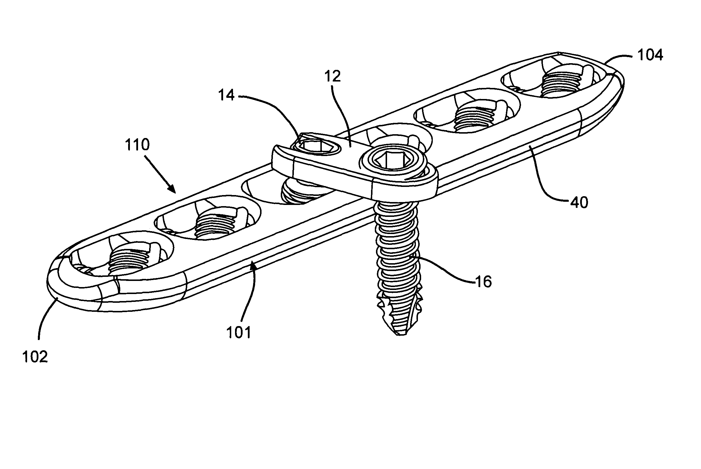
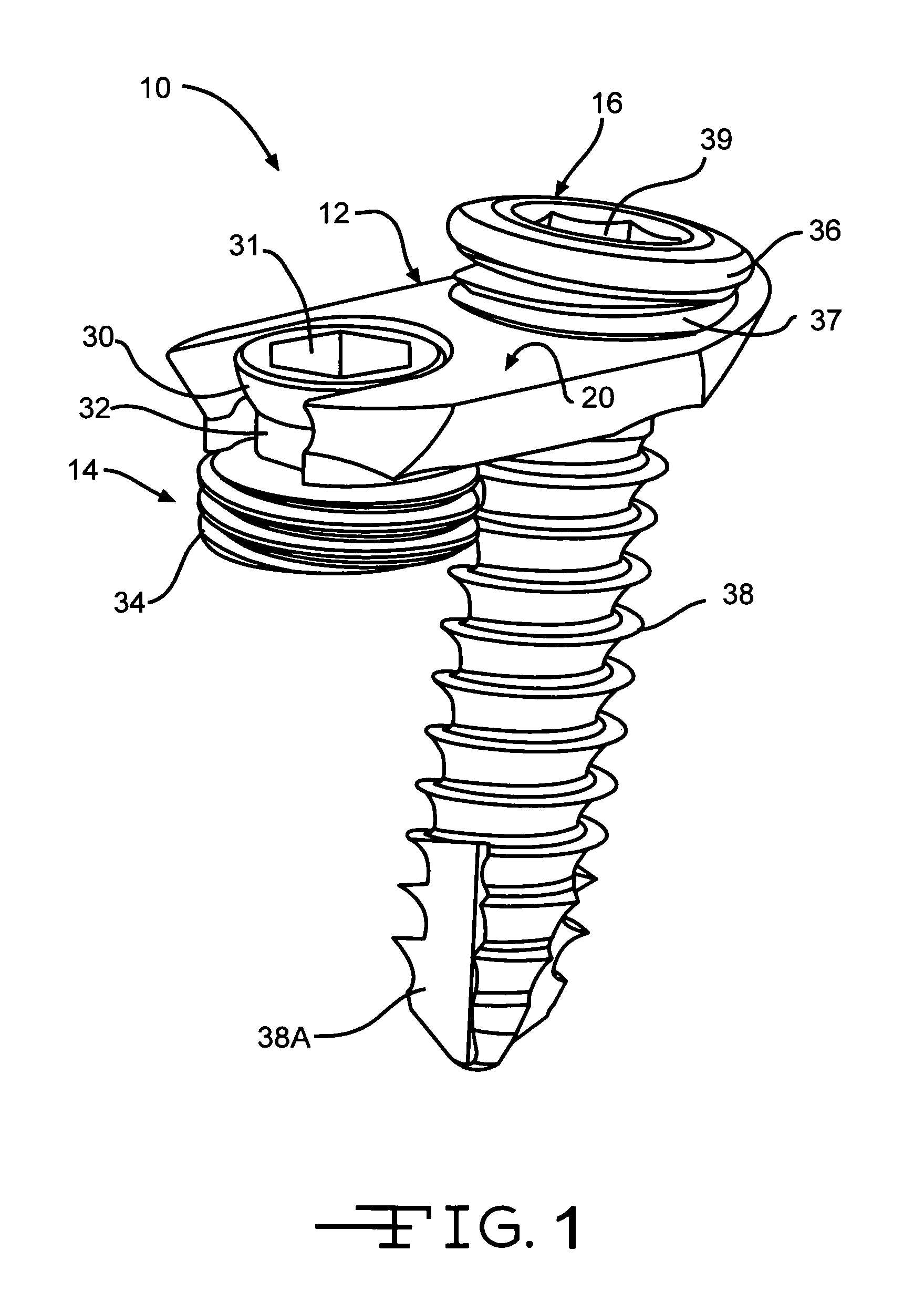
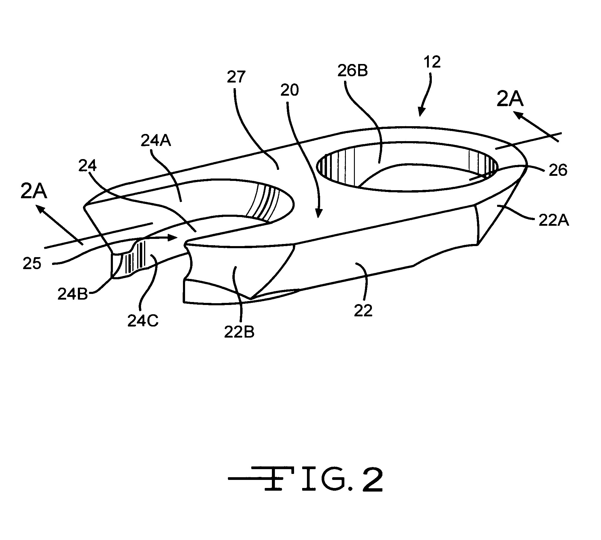
[0037]FIG. 1 is a perspective view of an orthopedic bone plate insert device 10 according to the present invention. The insert device 10 comprises a bone plate insert 12, a set screw 14 and a locking screw 16.

[0038]The insert 12 is intended to fit tightly into the complex aperture 110 of a bone plate 40 as shown in FIG. 5. The bone plate 40 comprises a longitudinal axis, a bone-contacting bottom side and a top side with at least one complex apertures extending through the plate thickness from the top to bottom side thereof. The complex aperture 110 is comprised of at least one set of two immediately adjacent holes 112. Each hole 112 has a threaded surface formed therein adapted to lock with threads of a corresponding bone screw. Any two immediately adjacent holes of the complex aperture 110 comprise a compression ramp 116 extending from an oval shaped opening at the top side 106 of the plate downwardly and inwardly part way through the plate thickness to a lower portion having an ho...


PUM


Abstract

An improved insert for assembly with a bone plate is described. The insert has a first opening adapted to receive a set screw and a second opening adapted to receive a bone screw. The insert is connectable to the bone plate using a set screw. The insert in conjunction with the set screw provides an improved range of relative motion for placing the bone screw at outboard locations with respect to the bone plate. That way, bone fragments that are not necessarily reachable using the bone plate without the insert can be secured together for improved healing.

Description

CROSS-REFERENCE TO RELATED APPLICATION[0001]The present application claims priority from U.S. Provisional Application. Ser. No. 61 / 104,381, filed Oct. 10, 2008.BACKGROUND OF THE INVENTION[0002]1. Field of the Invention[0003]The present invention is related generally to implantable orthopaedic implants. More specifically, the present invention is related to implantable orthopaedic bone plate inserts.[0004]2. Background Art[0005]Orthopaedic bone plates play a critical role in the healing process of broken bones. Once a bone has been fragmented, it is ideal for the broken bone fragments to be joined back together under compression to promote improved healing. The bone plate is a critical device that is used as a stabilizing bar that bridges the gap in bringing the bone fragments together.[0006]During surgery, a bone plate is inserted next to the fragmented bone of a patient. Compression screws are first placed through the bone plate. They are then anchored into each of the bone fragmen...

Claims


Application Information

Patent Timeline
IPC IPC(8): A61B17/80
CPCA61B17/80A61B17/8061A61B17/8057
Inventor WHITE, PATRICK M.CHENAUX, FABRICEMERETTE, JEAN-SEBASTIEN
Owner VIANT AS&O HLDG LLC
Why Eureka
Try Eureka