
Apparatus for determining the presence of fog using image obtained by vehicle-mounted imaging device

a vehicle-mounted imaging and fog detection technology, applied in scene recognition, television systems, instruments, etc., can solve the problems of human deaths and property damage, difficult accurately predicting visibility conditions, and inconvenient use, so as to reduce the error in determining whether or not fog is present, the effect of improving the accuracy of determination and reducing the value of luminan

Inactive Publication Date: 2014-07-22
DENSO CORP
View PDF27 Cites 17 Cited by
  • Summary
  • Abstract
  • Description
  • Claims
  • Application Information

AI Technical Summary

Benefits of technology

This approach reduces errors in fog detection and improves accuracy by masking high-luminance obstacles and focusing on luminance intensity, enabling reliable determination of fog presence even in dense conditions.

Problems solved by technology

Operators in automotive vehicles in foggy regions encounter hazardous poor visibility conditions.
However, poor visibility conditions often lead to traffic accidents causing human fatalities and property damage.
Although the accuracy of weather forecasting has steadily improved, accurately predicting visibility conditions is considered extremely difficult.
One of the difficulties lies in that poor visibility frequently occurs in localized areas as a result of microclimate changes in that region, and the condition change in a matter of minutes or seconds.
Information obtained by these perception sensors is utilized to perform automatic tasks such as turning on fog lamps or alerting the operator that the safety system installed in his vehicle is inoperative due to lack of sufficient information from the sensors.
Indeed, in a foggy environment, the operator actually tends to overestimate visibility distance and to drive his vehicle with excessive speed.
This fact lead to a more complex system when the method of Schechner et al. applies to a vehicle-mounted fog detecting system which is not suitable for practical purposes.
Further, the method of Schechner et al. may be less effective when illumination is less directional.
Therefore, for example in dense fog, an accurate determination of the presence of fog is difficult.
Second, if there is another vehicle in front of the vehicle and the other vehicle is emitting light from the tail lamp, it is difficult to determine the curve of luminosity.
In recognizing the white line on the road on which a vehicle is traveling based on an image captured by the vehicle-mounted camera, if fog is present in an atmosphere on the road, the image gets blurred with a resultant difficulty of recognizing the white line.

Method used


Image

  • Apparatus for determining the presence of fog using image obtained by vehicle-mounted imaging device
  • Apparatus for determining the presence of fog using image obtained by vehicle-mounted imaging device
  • Apparatus for determining the presence of fog using image obtained by vehicle-mounted imaging device

Examples


first embodiment

[0071]Referring to FIGS. 1 to 24, an apparatus according to a first embodiment of the present invention, which determines the presence of an element interfering with the visibility of a frontal view of an operator in an vehicle in an environmental atmosphere ahead of the vehicle equipped with the apparatus in the daytime, will be described below in detail.

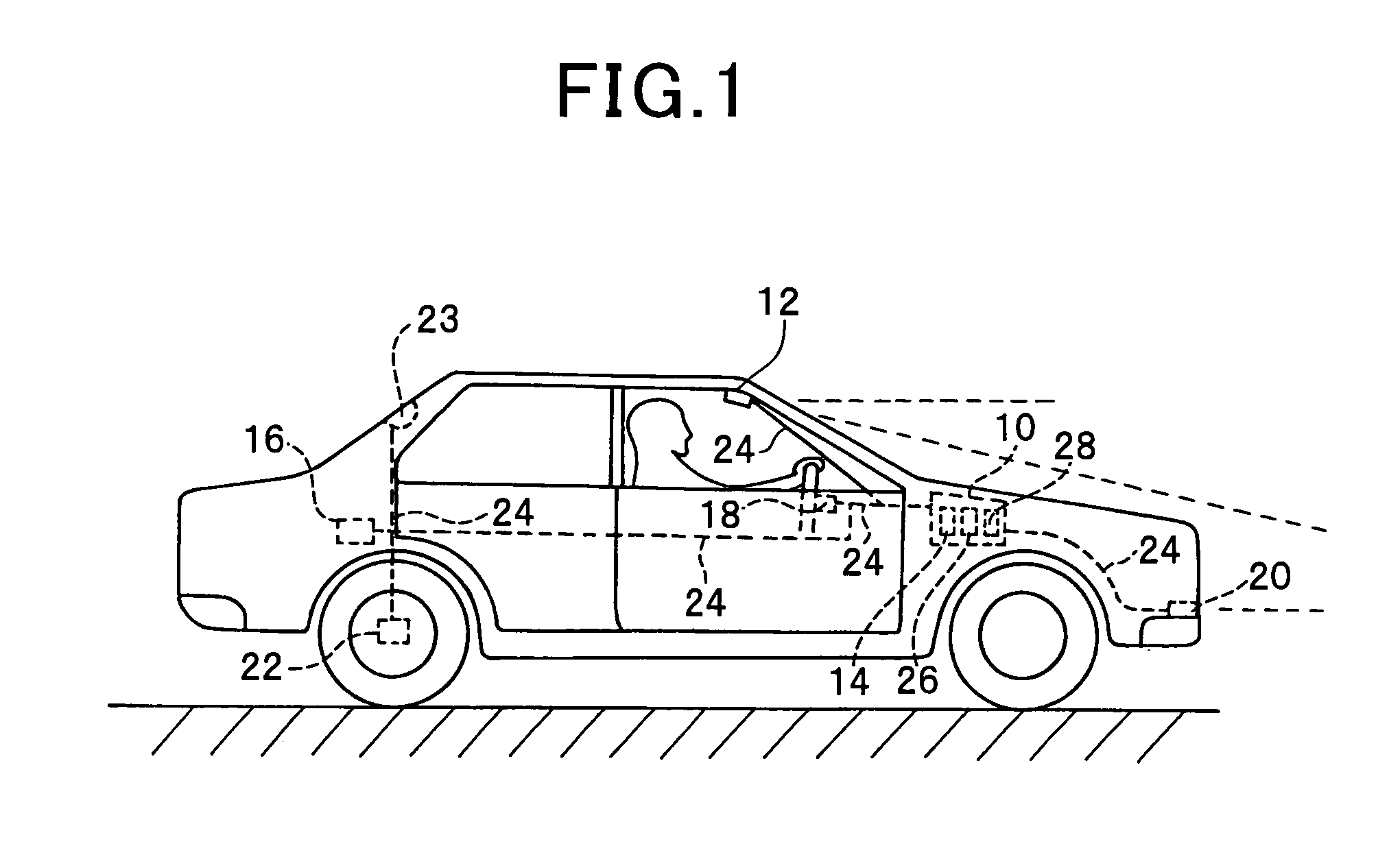
[0072]FIG. 1 is a schematic representation of a vehicle equipped with the apparatus 10 according to the first embodiment of the present invention.

[0073]The apparatus 10 is installed in the vehicle. The presence of an element such as fog leads to poor visibility of a road scene of an operator of the vehicle. Fog is an accumulation of water droplet or ice crystal fines accompanied by water-saturated fine particles that acts to reduce visibility. Thus fog's composition is identical to that of a cloud. In the presence of fog, visible light having a wavelength ranged between 400 and 700 nanometers must be propagated within an aerosol th...

second embodiment

[0159]Referring to FIGS. 25 to 28, a second embodiment of the present invention will be explained. The mechanical constituents of the second embodiment are the same members to those of the first embodiment, but the control operations of this embodiment are different from those of the first embodiment.

[0160]FIG. 25 is a block diagram showing a structure of a vehicle-mounted apparatus 14A according to the second embodiment of the present invention.

[0161]In the apparatus 14A, the spatial frequency analyzing block 14d in the first embodiment is replaced with an edge intensity analyzing block 14d′.

[0162]The edge intensity analysis is one of the methods for calculating a total edge intensity of an image. An individual edge intensity of the corresponding pixel in the image can be obtained by a differential calculus along a vertical or horizontal direction in the image.

[0163]It should be noted that in the edge intensity analysis, the degree of the discontinuities in a sweep-line can not af...

third embodiment

[0177]Referring to FIG. 29, a third embodiment of the present invention will be explained. The mechanical constituents of the third embodiment are the same members to those of the first and second embodiments, but the control operations of this embodiment are different from those of the first and second embodiments.

[0178]In this embodiment, the masking operation in step S200 in FIG. 4 is different with the previous embodiments. Therefore, the structure of the apparatus 10 is the same one with either that of the first embodiment shown in FIG. 3 or that of the second embodiment shown in FIG. 25.

[0179]Referring to FIG. 29, the masking operation according to this embodiment will be explained in detail.

[0180]FIG. 29 is a flowchart showing a detail of a masking operation in which pictures within the image having possibility to cause noises during image processing for determining the presence of fog will be removed in step S200 in FIG. 4.

[0181]The masking operation is started in step S210 ...


PUM


Abstract

An apparatus that detects the presence of a constituent such as fog affecting a view of space which is present ahead of a vehicle, the constituent resulting from a natural phenomenon in the space is provided. In this apparatus, the determination of whether the presence of the element is determined based on an image that captured by a vehicle-mounted camera and in which a picture of a high-luminance obstacle located on a road over which the vehicle is traveling is masked.

Description

CROSS REFERENCE TO RELATED APPLICATION[0001]The present application relates to and incorporates by references Japanese Patent Application No. 2007-3928 filed on Jan. 11, 2007.BACKGROUND OF THE INVENTION[0002]1. The Field of the Invention[0003]The present invention relates to an apparatus and method for determining whether or not fog is present in the environment around a vehicle based on an image which is captured by a vehicle-mounted imaging device such as a camera. For example, the present invention relates to a system and method for determining whether or not an image captured by a vehicle-mounted imaging device is hazed by the presence of fog in an environment around a moving vehicle using an image processing technique in which an high-luminance obstacle is masked.[0004]2. Description of the Related Art[0005]Operators in automotive vehicles in foggy regions encounter hazardous poor visibility conditions. In normal circumstances, an operator in an automotive vehicle gains knowled...

Claims


Application Information

Patent Timeline
Patent Type & Authority Patents(United States)
IPC IPC(8): H04N7/18
CPCG06K9/00805B60Q2300/312G06K9/00791G06K9/00825G06V20/58G06V20/584
Inventor KAWASAKI, NAOKI
Owner DENSO CORP
Learn More