Computer rack cooling using independently-controlled flow of coolants through a dual-section heat exchanger

a heat exchanger and rack cooling technology, applied in the field of computer rack cooling, can solve the problems of affecting the total cost of ownership of datacenter equipment, generating a considerable amount of heat,

Active Publication Date: 2014-07-29
LENOVO GLOBAL TECH INT LTD
View PDF32 Cites 61 Cited by
  • Summary
  • Abstract
  • Description
  • Claims
  • Application Information

AI Technical Summary

Problems solved by technology

Rack-based computer systems include many rack-mounted components in a high-density arrangement, which can produce a considerable amount of heat.
Energy efficiency in a datacenter dramatically affects the total cost of ownership of datacenter equipment.

Method used


Image

  • Computer rack cooling using independently-controlled flow of coolants through a dual-section heat exchanger
  • Computer rack cooling using independently-controlled flow of coolants through a dual-section heat exchanger
  • Computer rack cooling using independently-controlled flow of coolants through a dual-section heat exchanger

Examples


Embodiment Construction

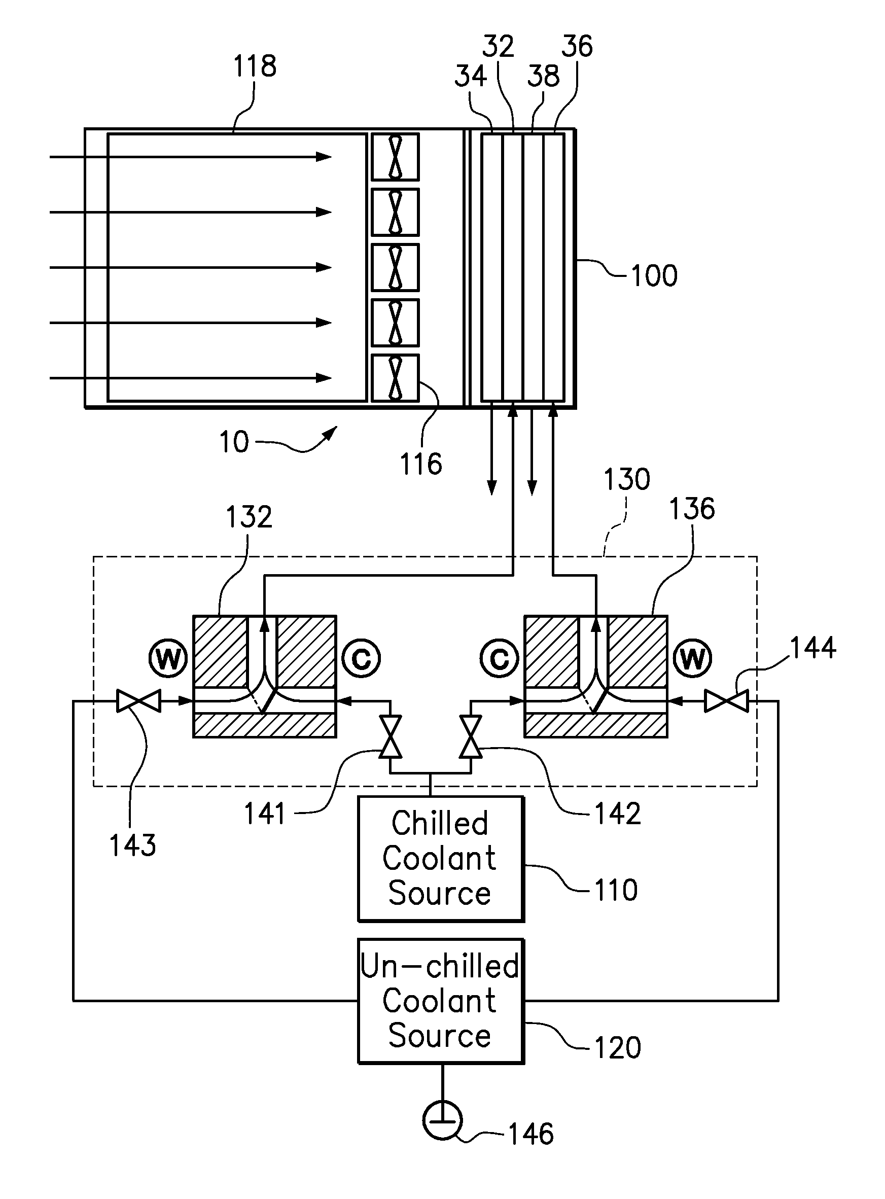
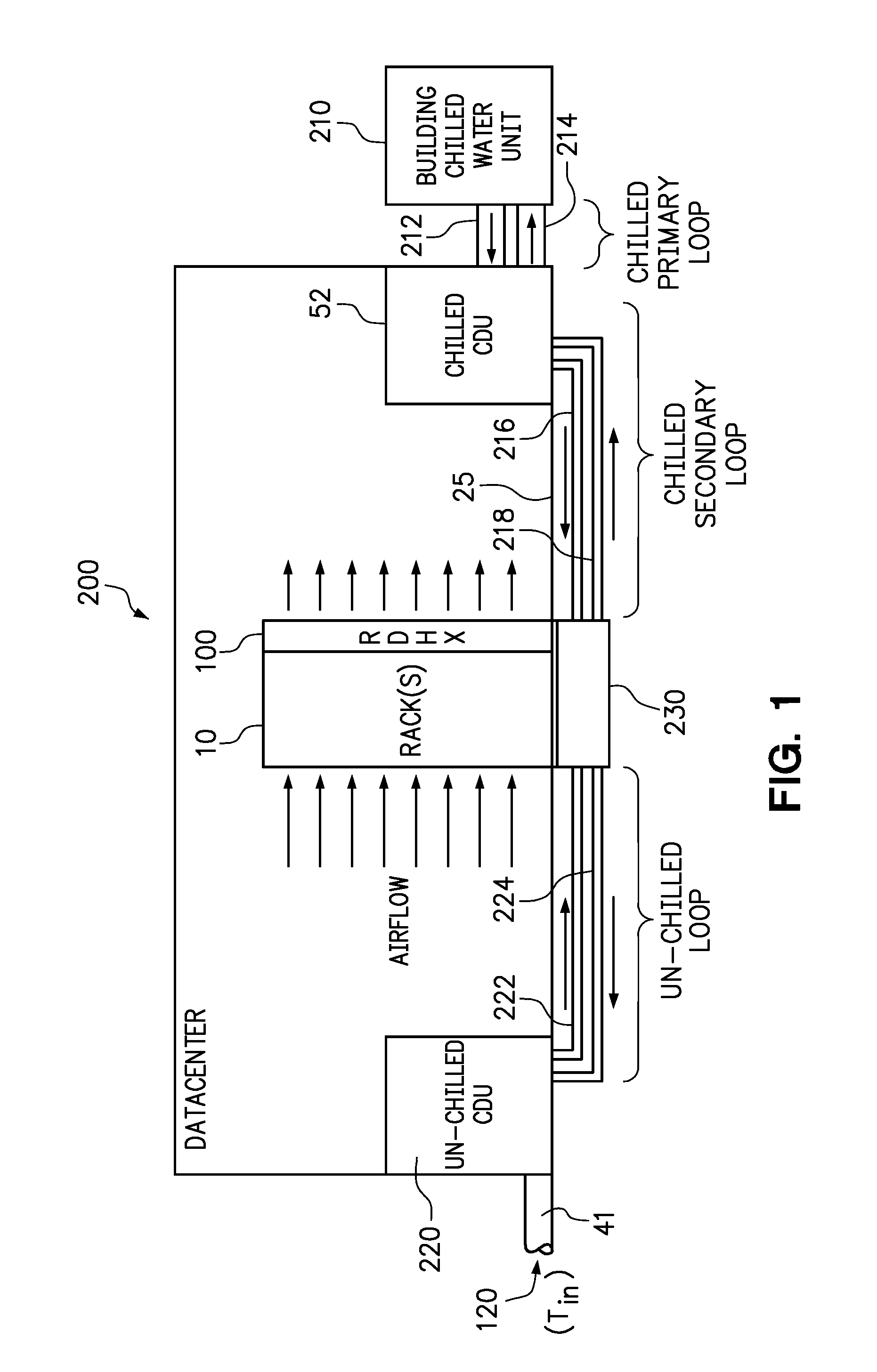
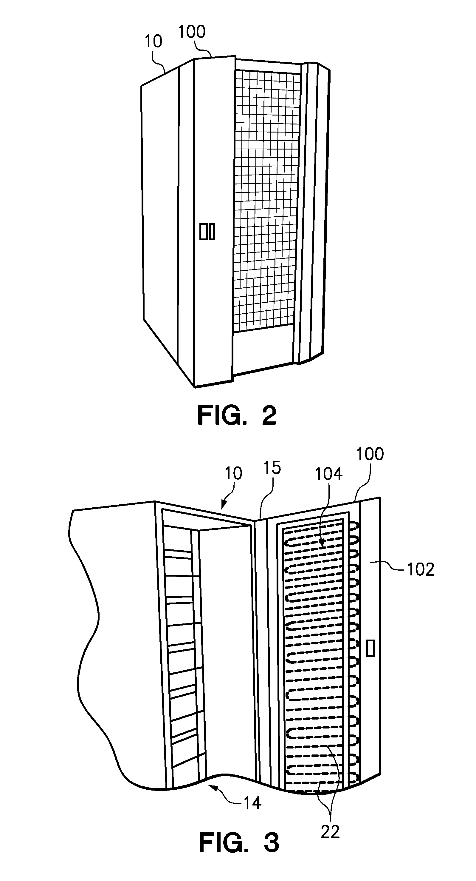
[0018]Embodiments of the present invention include a cooling system and method for cooling a computer rack by circulating liquid coolant through different sections of a rack heat exchanger under separately controlled flow and temperature conditions. In one embodiment, a rear door heat exchanger includes two heat exchanger sections. Each section is supplied by a coolant from the same source or different sources, for example with one source providing chilled coolant and the other section providing un-chilled coolant. Each section may have one or more layers of cooling tubes. The cooling tubes in each section define a plurality of fluid circuits. Each circuit typically passes through multiple layers from an inlet manifold to an outlet manifold, making one or more passes across the heat exchanger within each layer. The flow rate of coolant to each section is individually controlled to enforce a target cooling parameter, such as a target exit air temperature of airflow exiting the rack o...


PUM


Abstract

Embodiments of the present invention include a cooling system and method for cooling a computer rack by circulating liquid coolant through different sections of a rack heat exchanger under separately controlled flow and temperature conditions. In a method according to one embodiment, a first liquid coolant is supplied to a first section of an air-to-liquid heat exchanger. A second liquid coolant is supplied to a second section of the air-to-liquid heat exchanger at a different temperature than the first liquid coolant. Airflow is generated through rack-mounted computer components to the first and second sections of the air-to-liquid heat exchanger. The flow rates of the first and second liquid coolants are independently controlled to enforce a target cooling parameter. The independent operation of the first and second fin tube sections allows for the increased use of un-chilled water without sacrificing heat removal objectives.

Description

BACKGROUND[0001]1. Field of the Invention[0002]The present invention relates to computer system cooling, particularly in the context of a rear-door heat exchanger.[0003]2. Background of the Related Art[0004]Computer systems use electrical energy and produce heat as a byproduct. Rack-based computer systems include many rack-mounted components in a high-density arrangement, which can produce a considerable amount of heat. Heat must be removed from the rack to control internal temperatures and to maintain system reliability, performance, and longevity. In a conventional rack-based computer system, rack-mounted fans move cool air through the rack to remove the heat and cool the components. The heated exhaust air is then transported to a computer-room air conditioner (“CRAC”), which cools the air before returning the cooled air to the data center. Energy efficiency in a datacenter dramatically affects the total cost of ownership of datacenter equipment.[0005]A rear-door heat exchanger (R...

Claims


Application Information

Patent Timeline
Patent Type & Authority Patents(United States)
IPC IPC(8): F25B27/00F25B7/00F25D23/12F28D15/00H05K7/20
CPCF28D1/0435F28D1/0477H05K7/2079
Inventor ECKBERG, ERIC A.KAMATH, VINODMAHANEY, JR., HOWARD V.MEGARITY, WILLIAM M.STEINKE, MARK E.
Owner LENOVO GLOBAL TECH INT LTD
Why Eureka
Try Eureka