
Housing for an exhaust gas-treating device and process for manufacturing same

a technology for treating devices and exhaust gas, which is applied in the field of housings for treating devices, can solve the problems of a comparatively large effort associated with the conventional manufacturing procedure of such housings, and achieve the effects of simple manufacturing process, favorable effect, and significant savings

Active Publication Date: 2014-07-29
EBERSPACHER EXHAUST TECH GMBH & CO KG
View PDF21 Cites 0 Cited by
  • Summary
  • Abstract
  • Description
  • Claims
  • Application Information

AI Technical Summary

Benefits of technology

The present invention provides an improved embodiment for a housing that can be manufactured at a low cost. The housing can be made from a tailored blank, which has different materials and wall thicknesses in different areas. By reducing the wall thickness of the jacket, significant savings can be made in material, weight, and costs. The use of a rolling method to manufacture the housing makes it easy to adapt to different rolling parameters for the jacket and ring body, making the manufacturing process even simpler and more cost-effective. Additionally, the invention allows for the manufacturing of a housing with different functions, such as an intake funnel and discharge funnel, in a single piece.

Problems solved by technology

This conventional procedure for manufacturing such a housing is associated with a comparatively great effort.

Method used


Image

  • Housing for an exhaust gas-treating device and process for manufacturing same
  • Housing for an exhaust gas-treating device and process for manufacturing same
  • Housing for an exhaust gas-treating device and process for manufacturing same

Examples


Embodiment Construction

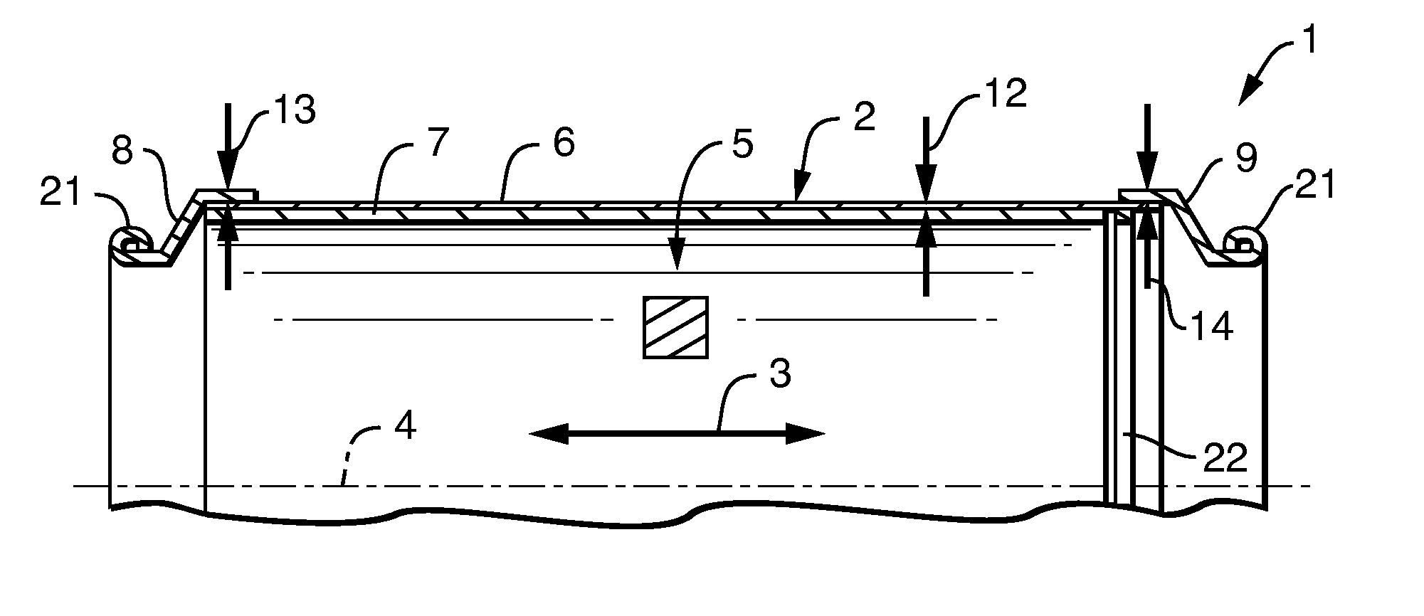
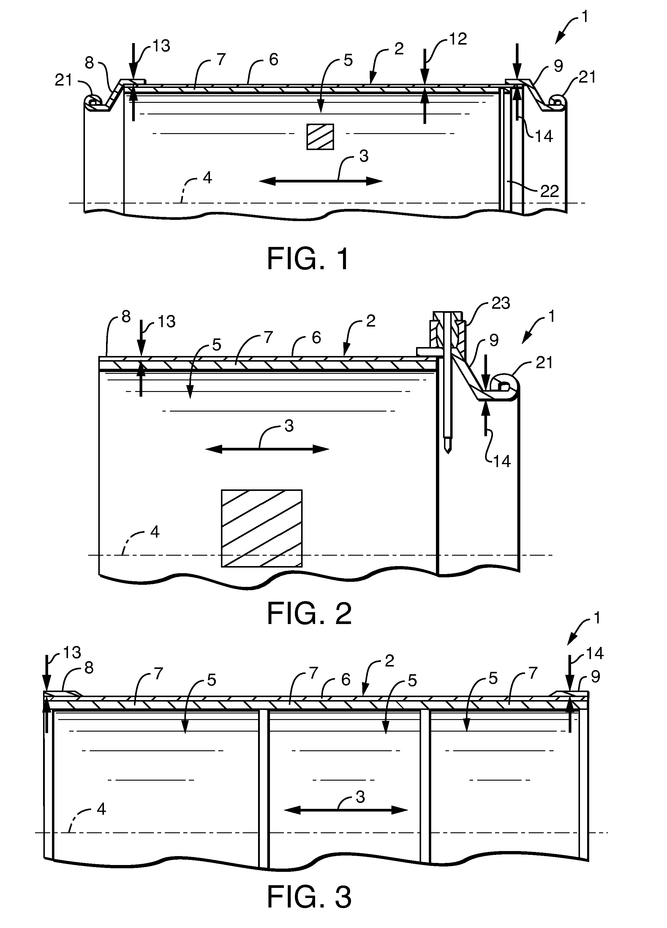
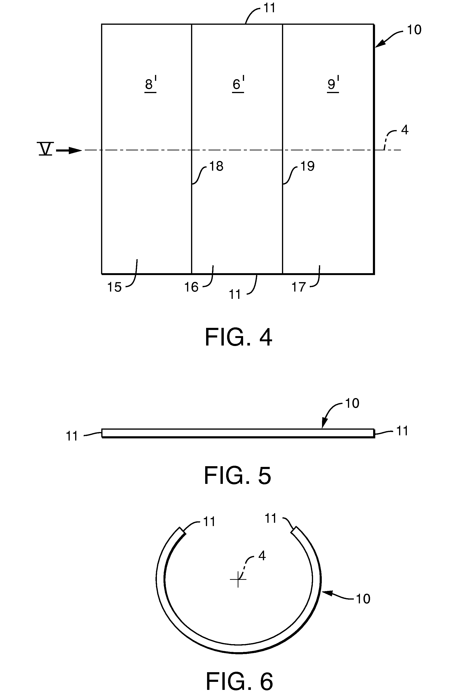
[0024]Referring to the drawings in particular, corresponding to FIGS. 1 through 3, an exhaust gas-treating device 1 comprises a housing 2, which is closed in the circumferential direction. This circumferential direction pertains here to a longitudinal or axial direction 3, which extends in parallel to a central longitudinal axis 4 of housing 2. The exhaust gas-treating device 1 may be, for example, a catalytic converter or a particle filter. Correspondingly, at least one exhaust gas-treating element 5, which may be, for example, a catalytic converter element or a particle filter element, is arranged in housing 2. The exhaust gas-treating device 1 is intended for use in an exhaust system of an internal combustion engine, and the internal combustion engine may be preferably located in a motor vehicle.

[0025]Housing 2 comprises a jacket 6, which is closed in the circumferential direction and is designed to receive the at least one exhaust gas-treating element 5. Jacket 6 coaxially surro...


PUM

PropertyMeasurementUnit
thicknessesaaaaaaaaaa
thicknessaaaaaaaaaa
mechanical stressesaaaaaaaaaa

Abstract

A housing (2) for an exhaust gas-treating device (1) of an exhaust system of an internal combustion engine includes a jacket (6) closed in the circumferential direction for mounting at least one exhaust gas-treating element (5. The jacket passes over at at least one axial end into a ring body (8, 9). The ring body (8, 9) is closed in the circumferential direction. The housing (2) can be connected to another component of the exhaust system. A simplified manufacture is achieved if the jacket (6) and the at least one ring body (8, 9) are manufactured from a single sheet steel billet (10) by rolling the sheet steel billet (10) in the circumferential direction and by connecting abutting edges (11) of the sheet steel billet (10). The jacket (6) and the at least one ring body (8, 9) differ from one another by different materials and / or different wall thicknesses (12, 13, 14).

Description

CROSS REFERENCE TO RELATED APPLICATIONS[0001]This application claims the benefit of priority under 35 U.S.C. §119 of German Patent Application DE 10 2009 018 823.1 filed Apr. 24, 2009, the entire contents of which are incorporated herein by reference.FIELD OF THE INVENTION[0002]The present invention pertains to a housing for an exhaust gas-treating device of an exhaust system of an internal combustion engine. The present invention pertains, moreover, to a process for manufacturing such a housing.BACKGROUND OF THE INVENTION[0003]Housings of exhaust gas-treating device, for example, catalytic converters and particle filters, usually have a jacket closed in the circumferential direction for mounting at least one exhaust gas-treating element. This jacket may pass over at least at one axial end into a ring body, which is closed in the circumferential direction and is, for example, funnel-shaped, with which the housing can be connected to another component of the exhaust system. Furthermo...

Claims


Application Information

Patent Timeline
Patent Type & Authority Patents(United States)
IPC IPC(8): B01D50/00B21D51/16
CPCF01N3/2839F01N3/28F01N13/18F01N2450/00F01N2450/20F01N2450/22F01N2470/26Y10T29/49345Y10T29/49398
Inventor MULLER, BERNDBLUM, ACHIMPOTH, OLIVER
Owner EBERSPACHER EXHAUST TECH GMBH & CO KG
Learn More