Tool for connecting pipelines

a technology for connecting pipelines and tools, which is applied in the direction of pipe laying and repair, fluid removal, drilling machines and methods, etc., can solve the problems of vertical installations imposing heavy loads on the seabed structures, and achieve the effect of fewer parts and simple operation

Active Publication Date: 2014-08-05
FMC KONGSBERG SUS
View PDF23 Cites 15 Cited by
  • Summary
  • Abstract
  • Description
  • Claims
  • Application Information

AI Technical Summary

Benefits of technology

[0006]The present invention is an improvement on this system, having fewer parts and is much simpler to operate. Instead of using a special ROV tool to move the termination head towards the inboard hub ...

Problems solved by technology

Vertical installations can impose heavy loads on the seabed structures as they are landed and rotated.
The disadvantage wit...

Method used


Image

  • Tool for connecting pipelines
  • Tool for connecting pipelines
  • Tool for connecting pipelines

Examples


Embodiment Construction

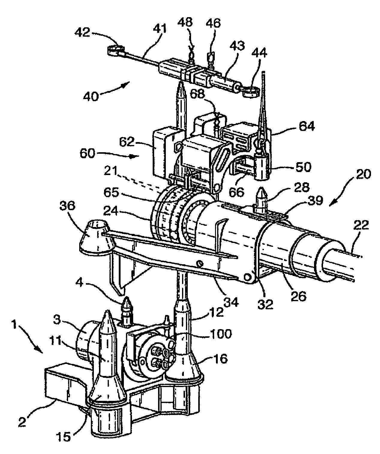
[0020]FIG. 1 is an assembly drawing showing the tools and structures used in the tie-in system for the connection of two pipe line (spool) ends, which may be provided with hubs. A seabed structure 1 comprises a frame 2 that supports a pipe 3 shown with a hub end 5 (FIG. 2). The pipe may be insulated as shown on FIG. 1. This hub end is normally termed an inboard hub. Anchoring means 4 such as an anchoring pin is attached to the inboard hub 5, protruding upwards. Also supported by the frame 2 are guide elements 11, 12, here shown as guide posts located at each side of the inboard hub. Each guide element (post) 11, 12 extend upwards and terminate in a point. At their base they have a portion 15, 16 that acts as supports. Their function will be described later. In the embodiment of FIG. 1 they are shown as conical mounts, but they may also be formed as plates or other structures providing support to the guide elements, preferably by being provided as an enlarged cross section area. In t...


PUM


Abstract

The invention concerns a tool for a tool for connecting an end of a first pipeline (22) to an end of a second pipeline (3) supported by a subsea structure (1) and being provided by at least two guide elements (11, 12). The tool comprising means for connecting the pipelines, and it comprises a receiving portion (32) provided to accommodate the end of the first pipeline in a slideable manner, and guiding means comprising at least two guiding sections (34, 35) extending from receiving portion (32). Each guiding section has an end arranged with an attachment portion (36, 37) interfacing with the guide elements (11, 12).

Description

BACKGROUND OF THE INVENTION[0001]The invention concerns a tool for connecting an end of a first pipeline to an end of a second pipeline supported by a subsea structure and being provided by at least two guide elements. Further, the invention also concerns a method for connecting the ends of first and second pipeline, wherein the second pipeline is supported by a subsea structure and being provided by at least two guide elements, and a tool comprising means for connecting the pipeline ends.[0002]Subsea installations for oil and gas extraction are commonly connected together by pipes, commonly called pipeline (or flowline) spools. The connection may for example be between a well and a manifold, or flowline (having a T-junction), or between template systems. In this case a length of pipe (a spool) is made on the surface, in each case fabricated to fit the distance between the hubs provided at the end of the pipelines. A termination head is normally fitted to each end of the spool. Ther...

Claims


Application Information

Patent Timeline
IPC IPC(8): E21B7/12E21B43/013F16L1/26
CPCF16L1/26E21B43/013
Inventor BEKKEVOLD KNUT H{DOT OVER (A)}VARD
Owner FMC KONGSBERG SUS
Why Eureka
Try Eureka