System and method for recycling of carbon-containing materials

a carbon-containing material and recycling technology, applied in the field of carbon-containing material recycling, can solve the problems of long-standing disposal problems, substantial reduction of disposal opportunities, and consequent increase of disposal costs, and achieve the effect of increasing the rate of pyrolysis

Active Publication Date: 2014-08-05
USED TIRE DISTILLATION RES
View PDF12 Cites 10 Cited by
  • Summary
  • Abstract
  • Description
  • Claims
  • Application Information

AI Technical Summary

Benefits of technology

[0018]The system may be operable to extract the carbon-containing gases from the upstream end of the heating arrangement for supply to the condensing arrangement. It has been surprisingly found by the inventors that withdrawal of the gases from the upstream end results in the gases containing less particulate matter, such as carbon particles. It will be appreciated that this is advantageous as any particulate matter in the gases extracted will generally need to be removed, for example, by use of filters.
[0019]The recirculating arrangement may be operable to recirculate the non-condensed gases to the heating arrangement by introducing the non-condensed gases into the heating arrangement upstream of the discharge arrangement, between the upstream and downstream ends of the heating arrangement and / or proximal to the upstream end. It will also be appreciated that the use of the recirculated gases provides for a number of advantages. Firstly, where the gas is introduced proximal to the upstream end, it may be used to heat, preferably rapidly heat (more preferably to temperatures in excess of 200 to 300° C.), the carbon-containing feed, thereby both increasing the rate of pyrolysis, and reducing the likelihood of the carbon-containing feed ‘sticking’ to the surfaces of the reactor. A further benefit is that the gas, which is still hot, may be used to maintain the internal temperature of the reactor. This is particularly useful where the heating means does not provide uniform heat to the reactor, for example, where a rotary kiln is used.
[0033]Where the heating arrangement comprises a rotary kiln, the arrangement is advantageously able to move the carbon-containing material through the kiln without the need for extra mechanical means, for example, a screw thread. This is particularly advantageous as pre-treatment of the material to remove large pieces of metal can be avoided.
[0045]It has been found that the systems and methods of the present inventions provide a quality of carbon black not obtained using hitherto known processes, as a result of the product being drier, and comprising fewer residues due to improved vapour extraction. The carbon black may be used as a filler or colouring agent for rubbers and plastics; as a colouring agent for inks, dyes, pigments and dispersions; and even as a fuel additive.
[0049]Still a further benefit is that the oil obtained is relatively low in sulphur compounds (e.g. less than 0.8% sulphur), meaning that further expensive processing to remove such compounds is likely unnecessary.

Problems solved by technology

The disposal of carbon-containing materials, such as used vehicle tyres and plastics used in the fabrication of vehicles, has been a long standing problem.
A European Directive banning the disposal of used vehicle tyres in landfill sites has substantially reduced the opportunities for disposal.
Disposal costs have consequently increased and there is, thus a greater, incentive to dispose of used tyres by illegal dumping, and / or the formation of tyre mountains.
Further, the End-of-Life Vehicles Directive is also making it more difficult for vehicle dismantlers to dispose of plastics materials used in the fabrication of vehicles.

Method used


Image

  • System and method for recycling of carbon-containing materials
  • System and method for recycling of carbon-containing materials
  • System and method for recycling of carbon-containing materials

Examples


Embodiment Construction

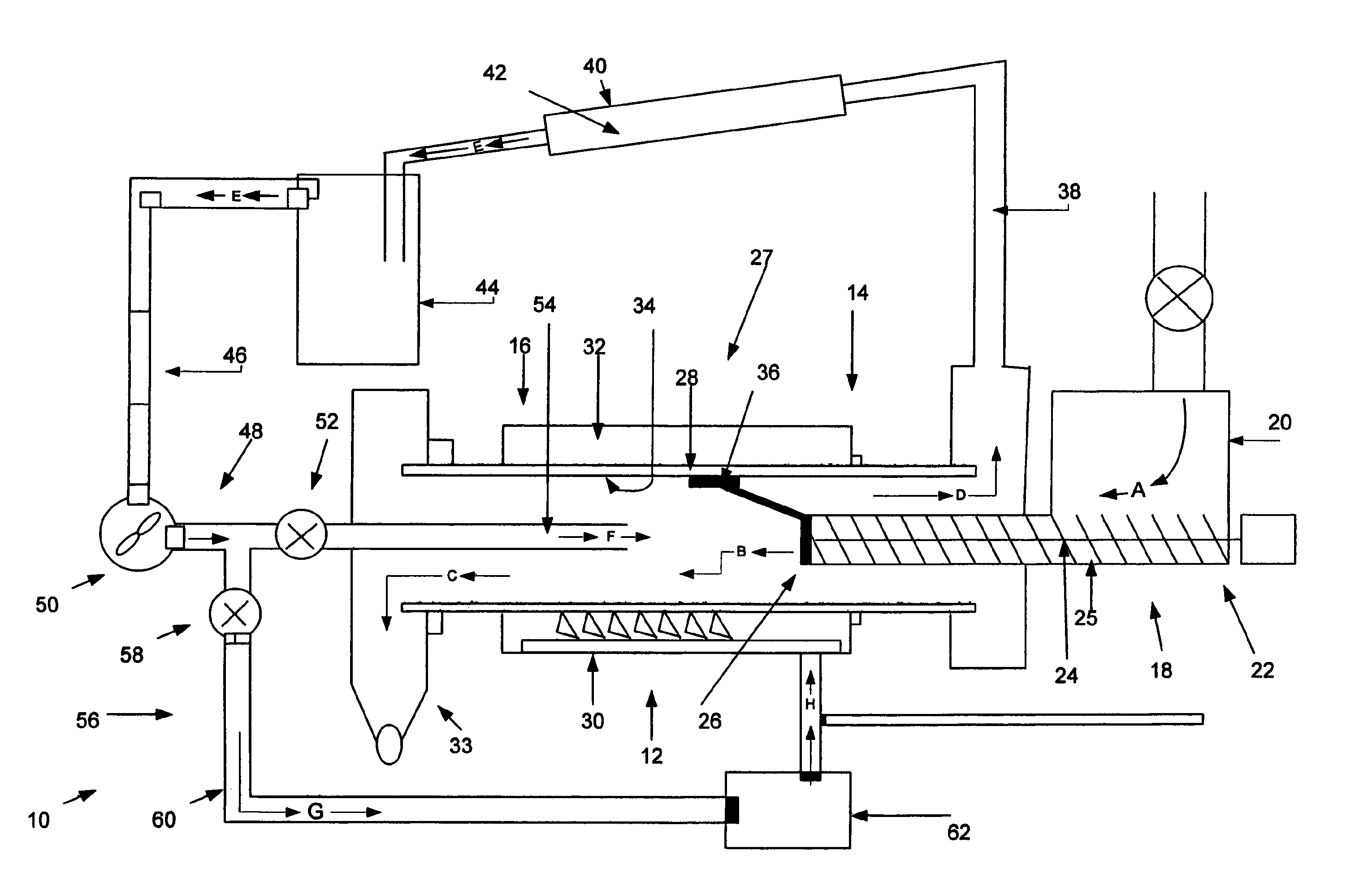
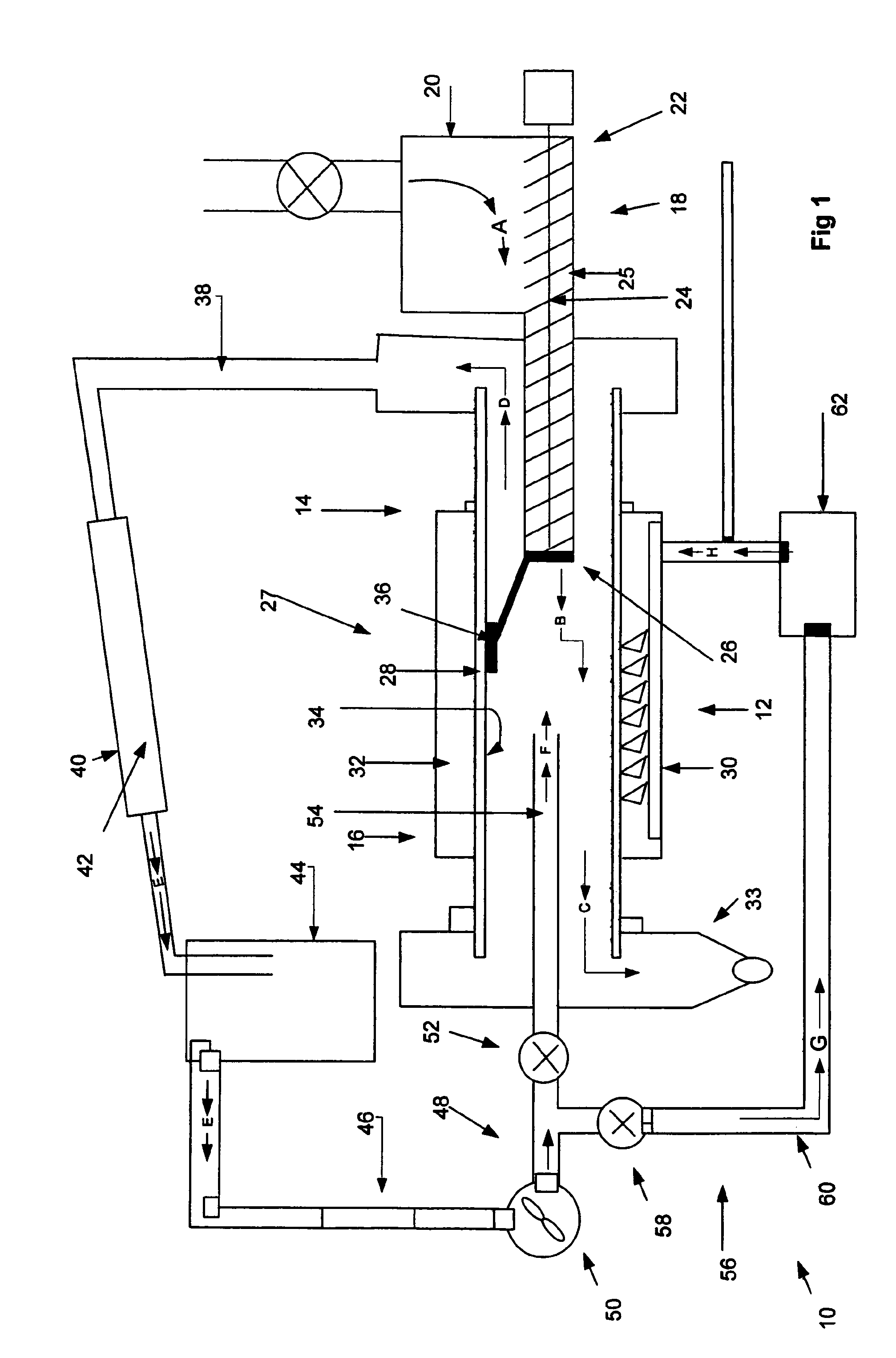
[0054]FIG. 1 shows a system 10 for recycling carbon-containing material. Examples of such carbon-containing material include, but are not limited to, waste tyres, waste plastics, tyre shred, rubber crumb and animal waste.

[0055]The system 10 includes a heating arrangement, i.e. a pyrolysis reactor, 12 having upstream and downstream ends 14, 16 and a feed arrangement 18 for feeding carbon-containing material into the heating arrangement 12. The feed arrangement 18 includes a feed source 20, such as a hopper, for supplying pieces of carbon-containing material to an input end 22 of a rotatable screw 24 located inside a static feed tube 25. This is indicated by the arrows A.

[0056]In the present invention, the diameter of the carbon-containing particle is from 30 to 300 mm, preferably 40 to 200 mm, and most preferably 50 to 150 mm. The individual pieces of carbon-containing material in the present example have a size in the order of 100 mm by 250 mm and these individual pieces are fed by ...


PUM

PropertyMeasurementUnit
temperatureaaaaaaaaaa
atmospheric pressureaaaaaaaaaa

Abstract

There is described a system and method for recycling carbon-containing material, in particular tires and plastics materials. The system includes a heating arrangement for anaerobically heating carbon containing material to produce carbon-containing gases. A condensing arrangement is also used to condense a proportion of the carbon-containing gases to provide condensed gases and non-condensed gases. In addition, a recirculating arrangement is provided for recirculating the non-condensed gases into the heating arrangement. Further systems and methods for pre- and post-processing of the carbon-containing material are also disclosed and products of the systems and methods are also described.

Description

FIELD OF THE INVENTION[0001]The present invention relates generally to recycling of carbon-containing materials, particularly vehicle tyres and plastics. More specifically, the present invention is directed to methods for recycling such carbon-containing materials, suitable apparatuses for processing these materials and to uses of such recycled materials.BACKGROUND TO THE INVENTION[0002]The disposal of carbon-containing materials, such as used vehicle tyres and plastics used in the fabrication of vehicles, has been a long standing problem. A European Directive banning the disposal of used vehicle tyres in landfill sites has substantially reduced the opportunities for disposal. Disposal costs have consequently increased and there is, thus a greater, incentive to dispose of used tyres by illegal dumping, and / or the formation of tyre mountains. The prices of oil and carbon black, both constituents of vehicle tyres, have also been gradually increasing.[0003]Further, the End-of-Life Vehi...

Claims


Application Information

Patent Timeline
Patent Type & Authority Patents(United States)
IPC IPC(8): C10B1/10C10B47/30C10B51/00C10B53/07C10G1/10
CPCC10B53/07C10G1/10C10B51/00C10B1/10C10B47/30C10G2300/202C10G2400/22C10G2300/1003C10G2400/20C10G2400/30C10G2300/4081Y02P20/143B09B3/00C10B53/00C10B57/00C10G1/00C10J3/00F23G5/00F23G7/00
Inventor HUTCHINS, RICHARDWALKER, MICHAELARCHER, PAUL
Owner USED TIRE DISTILLATION RES
Why Eureka
Try Eureka