Electrostatic orbital trap mass spectrometer

Active Publication Date: 2014-08-05
SCI & ENG SERVICES
View PDF3 Cites 12 Cited by
  • Summary
  • Abstract
  • Description
  • Claims
  • Application Information

AI Technical Summary

Benefits of technology

[0020]In one embodiment of the present invention, there is provided an orbital ion trap for electrostatic field ion trapping which includes an electrode structure defining an internal volume of the trap with at least some of electrode surfaces shaped to substantially follow equipotential lines of an ideal quadro-logarithmic electric potential around a longitudinal axis z. The ideal electric potential has an inner potential canyon, an outer potential canyon, and a low potential passage therebetween. The trap includes a trapping voltage sup

Problems solved by technology

As a result, the phases of oscillations for separate ions are spread out over the time and the coherent motion of the initially tight ion cloud disappears with time that limits the instrument mass resolution and accuracy.
As it was pointed out in U.S. Pat.

Method used


Image

  • Electrostatic orbital trap mass spectrometer
  • Electrostatic orbital trap mass spectrometer
  • Electrostatic orbital trap mass spectrometer

Examples


Embodiment Construction

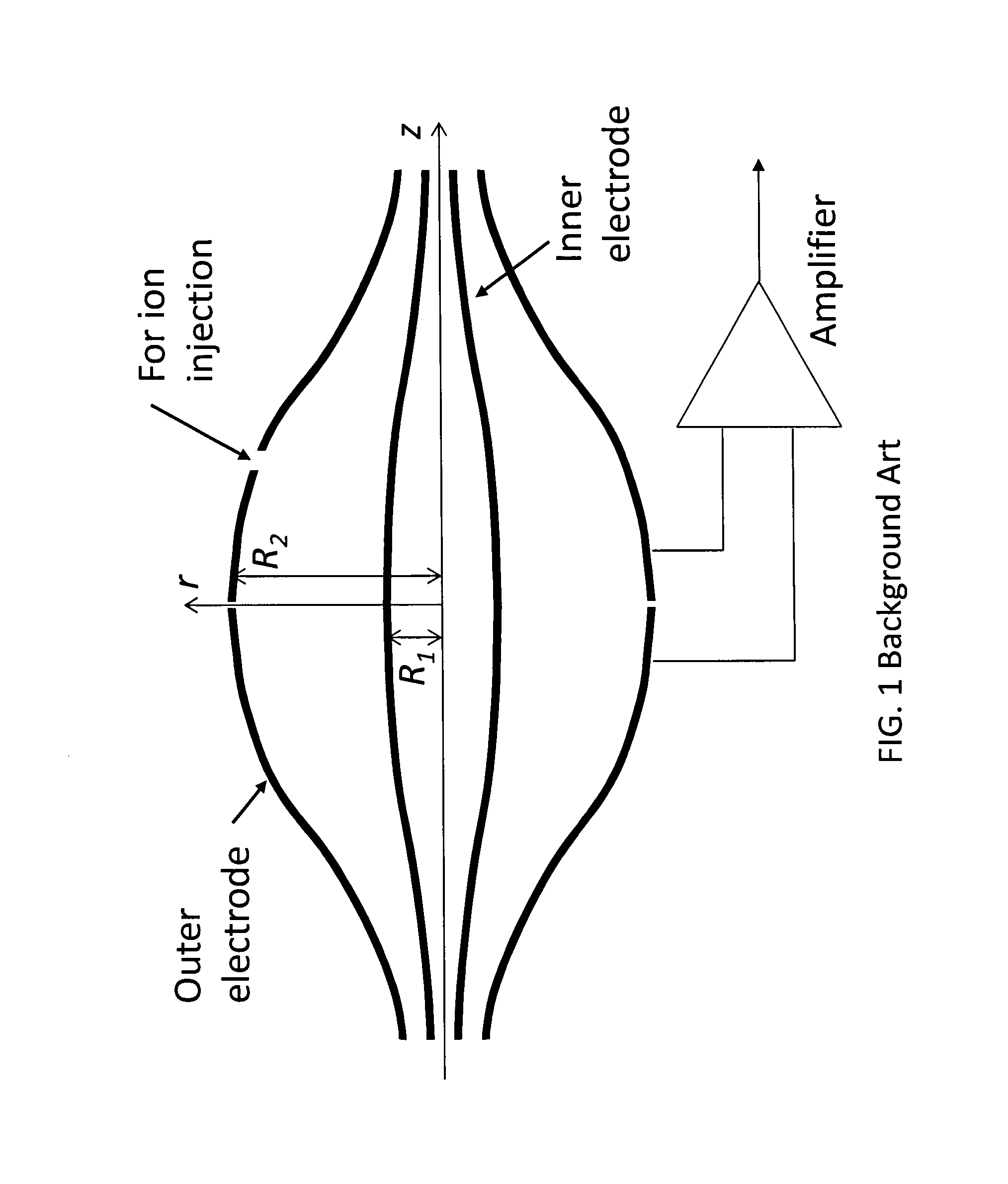
[0037]This invention addresses various problems in conventional high-performance mass spectrometers utilizing electrostatic orbital trap (OT) mass spectrometers (MS). For example, the effect of non-ideal approximation of the quadro-logarithmic potential in electrostatic orbital traps has been analyzed by Makarov et al. in U.S. Pat. No. 7,714,283. The truncation of the electrodes beyond some points along z axis has been shown to have relatively limited effect upon the ion phase spread discussed above. In particular, the shape of the trap near the electrode ends over the last 10% of its length (near the electrode ends) is largely irrelevant and according to Makarov there is no need to provide compensation (using extra electrodes) for the truncation of the inner and outer trap electrodes relative to their ideal infinite extent.

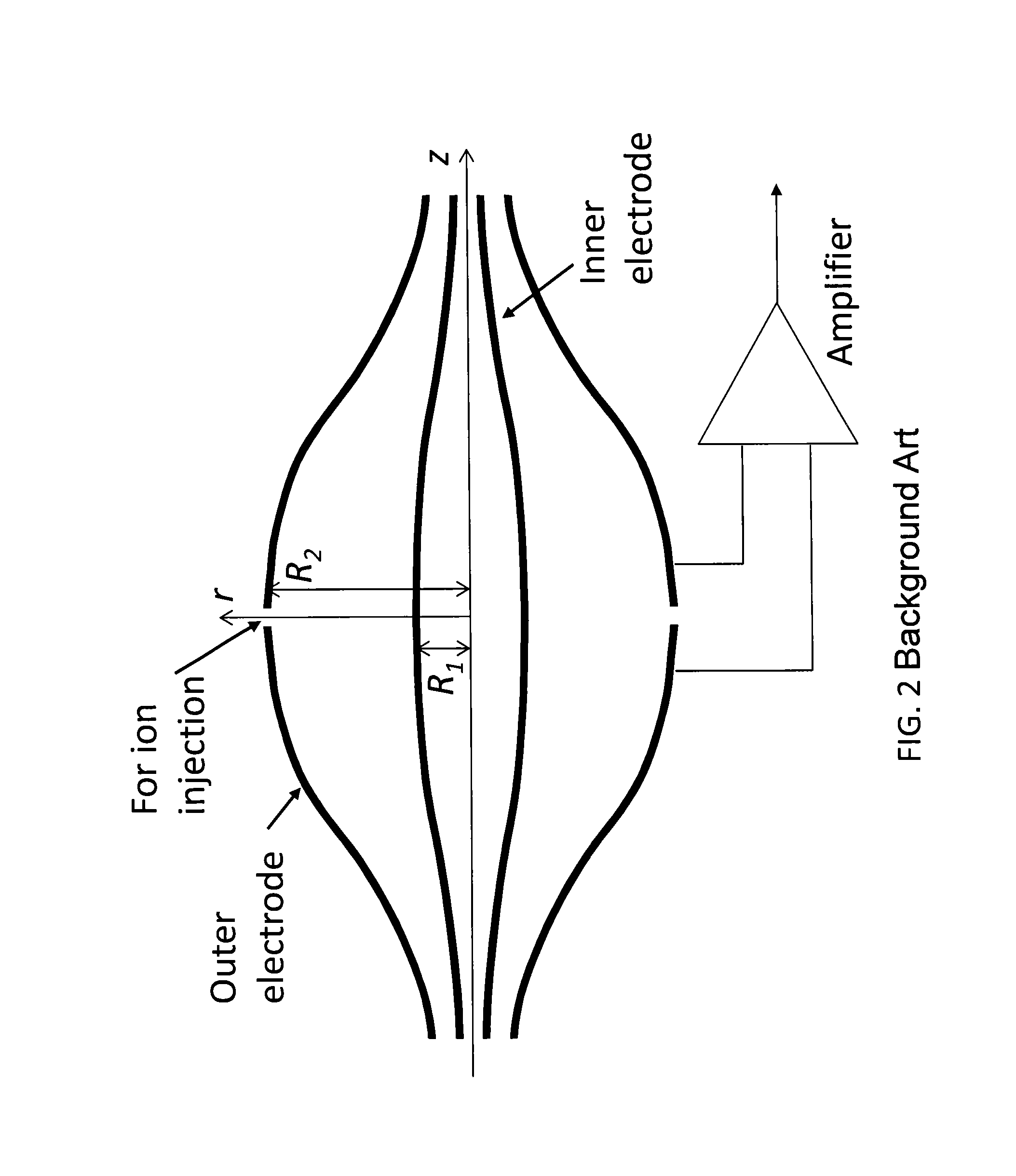
[0038]However, there are other features of the standard orbital trap (see FIG. 1) such as the injection slot and (to a lesser extent) the central slit between th...


PUM


Abstract

An orbital ion trap for electrostatic field ion trapping which includes an electrode structure defining an internal volume of the trap with at least some of electrode surfaces shaped to substantially follow equipotential lines of an ideal quadro-logarithmic electric potential around a longitudinal axis z. The ideal electric potential has an inner potential canyon, an outer potential canyon, and a low potential passage therebetween. The trap includes a trapping voltage supply which provides trapping voltages on the electrodes to generate a trapping electrostatic potential within the internal volume of the trap. The trapping electrostatic potential closely approximates at least a part of the ideal electric potential in at least a part of the internal volume of the trap.

Description

BACKGROUND OF THE INVENTION[0001]1. Field of the Invention[0002]This invention relates to mass spectrometers and more specifically to electrostatic orbital trap (OT) mass spectrometers (MS), and methods and systems for the detection of ions in mass spectrometers using orbital traps.[0003]2. Description of the Related Art[0004]In a high-performance Fourier transform (FT) mass spectrometer (MS), the mass-specific oscillating motions of the ions in a magnetic and / or electric fields are detected as image currents induced by the ions in detection electrodes. High-performance mass spectrometry is typically understood in the art to be a technique which typically is capable of achieving mass resolving power of at least 20,000 (using a FWHM—full width at half maximum, definition) and mass accuracy of 20 ppm or better. The entire contents of all references cited below are incorporated herein by reference in their entirety.[0005]There are two major classes of the high-performance FTMS instrume...

Claims


Application Information

Patent Timeline
IPC IPC(8): H01J49/26H01J49/42H01J3/00
CPCH01J49/26H01J49/42H01J3/40H01J49/425
Inventor DOROSHENKO, VLADIMIR M.MISHARIN, ALEXANDER
Owner SCI & ENG SERVICES
Why Eureka
Try Eureka