Reverse conductive nano array and manufacturing method of the same

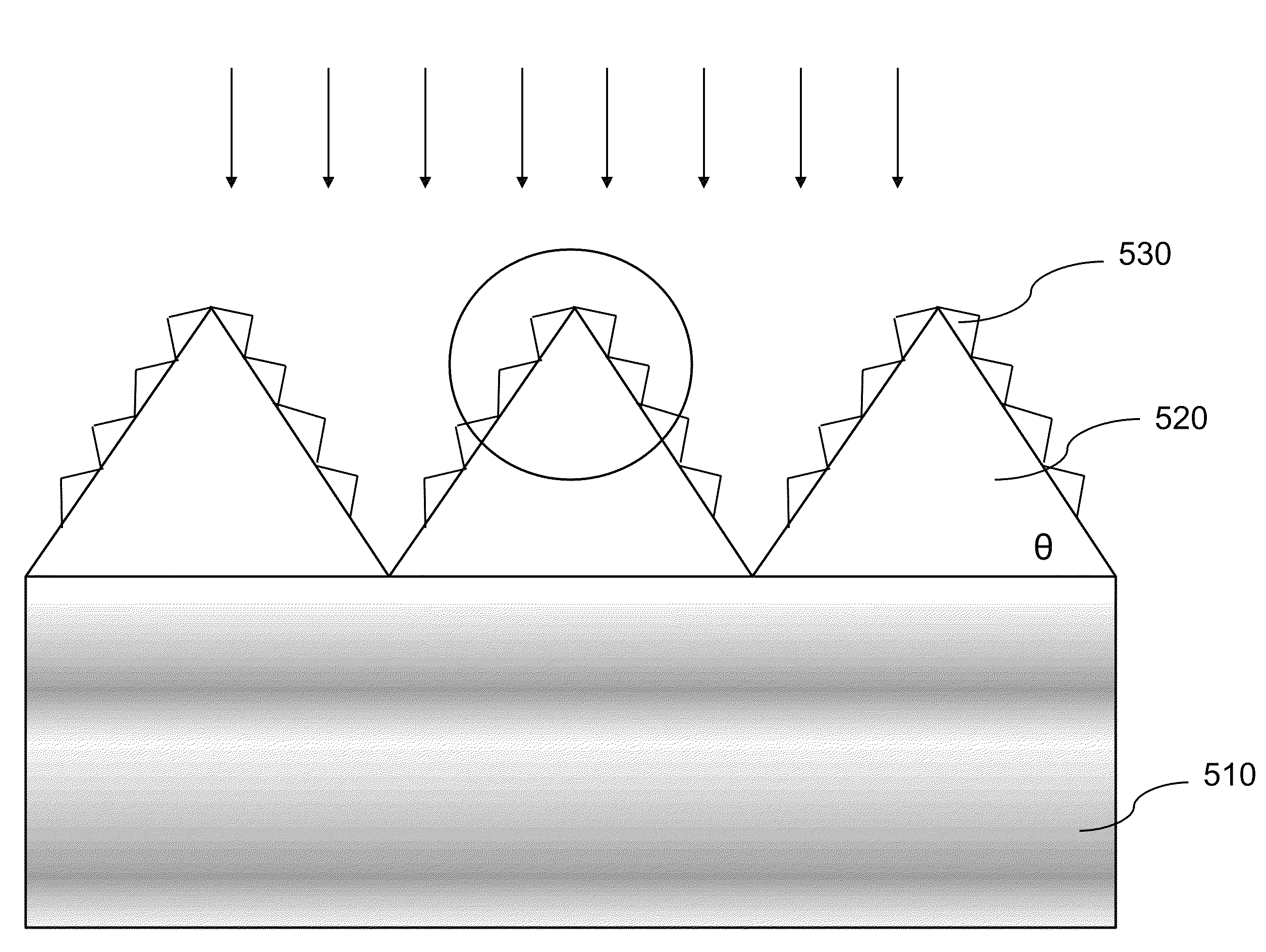
a nano array and reverse conductive technology, applied in the field of high-speed photodiodes, can solve the problems of reducing the speed of the photodiode, limiting the transit time of electrons and holes generated by incident light, etc., and achieves the effect of increasing the light path of incident light and high absorption efficiency

Inactive Publication Date: 2014-08-05
ZHEJIANG GUANGTE TECH CO LTD
View PDF8 Cites 1 Cited by
  • Summary
  • Abstract
  • Description
  • Claims
  • Application Information

AI Technical Summary

Benefits of technology

[0007]It is an object of the present invention to provide a high-speed photodiode device with high absorption efficiencies by increasing the light path of the incident light.
[0008]It is another object of the present invention to provide a high-speed photodiode device having a light-directing layer with a micro / nano-textured surface to change the angle of the incident light, and further increase the light path thereof.
[0010]It is still a further object of the present invention to provide a PIN diode employing a light-directing layer with a micro / nano-textured surface to change the angle of the incident light, and further increase the light path thereof.
[0011]It is still a further object of the present invention to provide an avalanche photodiode (APD) employing a light-directing layer with a micro / nano-textured surface to change the angle of the incident light, and further increase the light path thereof.
[0014]In another embodiment, a plurality of sub-triangular projections may be patterned on both sides of each triangular projection using nanolithography instruments including contact aligners, steppers or E-beam lithography. Furthermore, the incident light can be arranged to totally reflect in the triangular projection to significantly increase the light path when the refractive index of the sub-triangular projection is higher than the refractive index of corresponding triangular projection.

Problems solved by technology

To enhance the absorption efficiency, some people proposed to increase the thickness of the light-absorbing layer, however, it limits the transit time of electrons and holes generated by the incident light and thus reduce the speed of the photodiode.

Method used


Image

  • Reverse conductive nano array and manufacturing method of the same
  • Reverse conductive nano array and manufacturing method of the same
  • Reverse conductive nano array and manufacturing method of the same

Examples


Embodiment Construction

[0027]The detailed description set forth below is intended as a description of the presently exemplary device provided in accordance with aspects of the present invention and is not intended to represent the only forms in which the present invention may be prepared or utilized. It is to be understood, rather, that the same or equivalent functions and components may be accomplished by different embodiments that are also intended to be encompassed within the spirit and scope of the invention.

[0028]Unless defined otherwise, all technical and scientific terms used herein have the same meaning as commonly understood to one of ordinary skill in the art to which this invention belongs. Although any methods, devices and materials similar or equivalent to those described can be used in the practice or testing of the invention, the exemplary methods, devices and materials are now described.

[0029]All publications mentioned are incorporated by reference for the purpose of describing and disclos...


PUM


Abstract

A high-speed photodiode may include a photodiode structure having a substrate, a light-absorbing layer and a light-directing layer that is deposited on a top surface of the photodiode structure and patterned to form a textured surface used to change the angle of incident light to increase a light path of the incident light when entering the photodiode structure. In one embodiment, the light-directing layer may include a plurality of polygon such as triangular projections to refract the incident light to increase the light path thereof when entering the photodiode structure. In another embodiment, a plurality of nanoscaled sub-triangular projections can patterned on both sides of each triangular projection to more effectively increase the light paths. In a further embodiment, porous materials can be used to form the light-directing layer.

Description

FIELD OF THE INVENTION[0001]The present invention relates to opto-electronic devices, and more particularly to a high-speed photodiode having high absorption efficiencies without compromising the speed of the photodiode.BACKGROUND OF THE INVENTION[0002]Over the past few decades, photodiodes have been utilized in the areas including military, communication, information technology and energy. Photodiodes are operated by absorbing photons or charged particles to generate a flow of current in an external circuit, proportional to the incident power. In other words, photodiodes primarily have two functions: the absorption and conversion of light to an electrical signal, and the amplification of that electrical signal through multiplication.[0003]The application of photodiodes in optical telecommunication can be seen in FIG. 1, where an electrical signal is converted into an optical signal at a transmitting end and then transmitted through an optical transmission line, such as an optical f...

Claims


Application Information

Patent Timeline
Patent Type & Authority Patents(United States)
IPC IPC(8): H01L31/0236
CPCY02E10/50H01L31/02327H01L31/1075
Inventor LIAO, SHIRONGYE, JINLINLIAO, BODONG, JIE
Owner ZHEJIANG GUANGTE TECH CO LTD
Why Eureka
Try Eureka