Positioning device comprising a light beam

a technology of positioning device and light beam, applied in the field of metals, can solve the problems of large error of encoder, high cost, cumbersome and cumbersome, etc., and achieve the effect of reducing the speckle

Active Publication Date: 2014-12-18
CSEM CENT SUISSE DELECTRONIQUE & DE MICROTECHNIQUE SA RECH & DEV
View PDF1 Cites 2 Cited by
  • Summary
  • Abstract
  • Description
  • Claims
  • Application Information

AI Technical Summary

Benefits of technology

[0021]In one embodiment the speckle reduction means comprises a vibration system attached to the diffusing plate. In another embodiment an acousto-optic system produces an oscillation of the light spot on the diffusing plate to reduce the speckle effect.

Problems solved by technology

These systems have fundamental drawbacks.
Either they are simple and the possible resolution is not very high, typically 0.1 micron at most, or the resolution is very high, typically 1 nm, and the system therefore is very complex, cumbersome and very expensive.
By combining different encoders, the errors of these encoders are added and the measurement precision is rarely better than half a micron.
Also, it is not always evident to combine linear and rotational encoders in the same space allocated to perform the 3D position or movement of an object.

Method used


Image

  • Positioning device comprising a light beam
  • Positioning device comprising a light beam
  • Positioning device comprising a light beam

Examples


Embodiment Construction

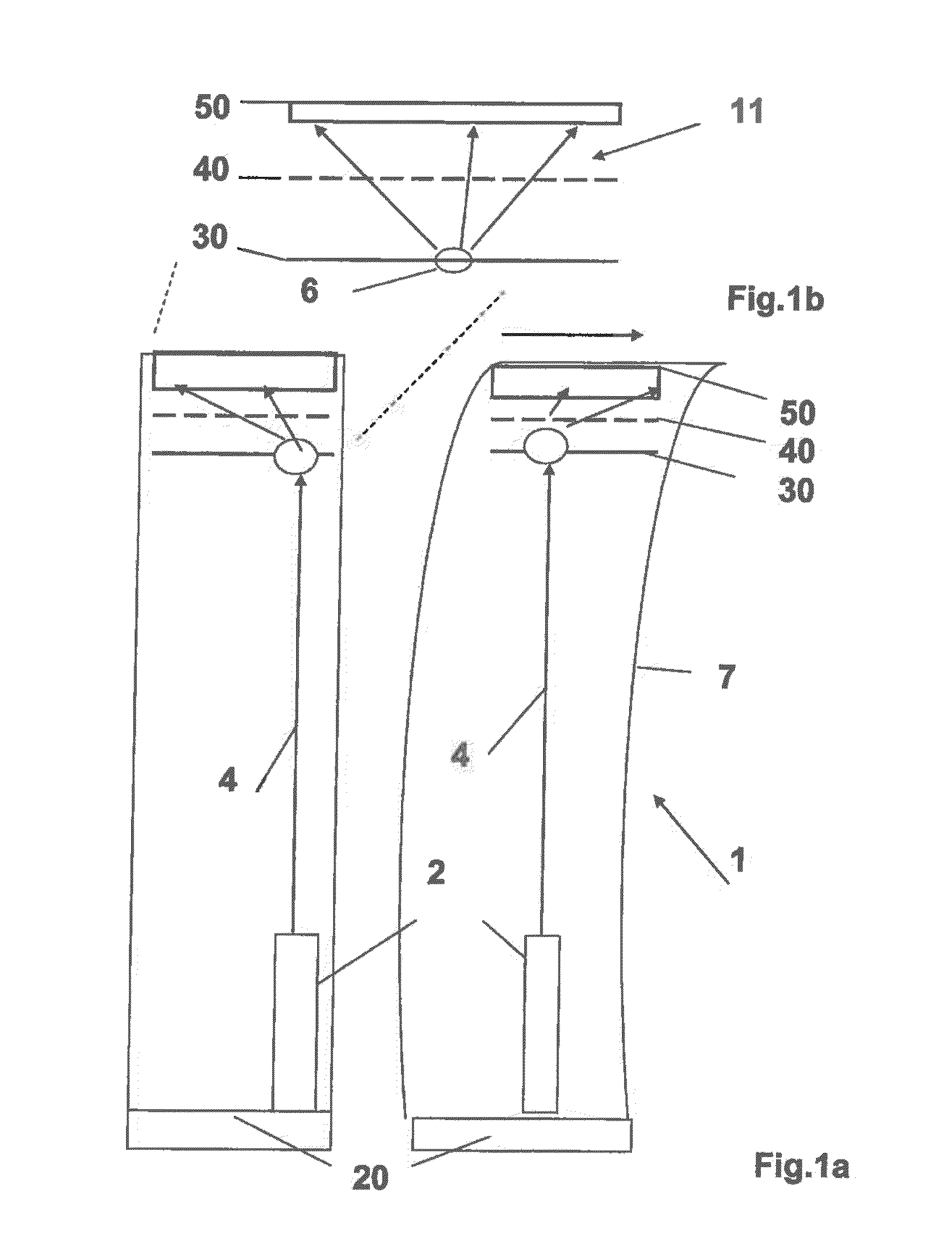
[0044]FIG. 1 illustrates the principle of the present invention of a position measurement system for determining 3D displacement and rotation of a mobile element with respect to a fixed reference frame 20. The proposed system 1 comprises, according to the invention:[0045]a point light source 2, preferably a point light source 2 fixed on a reference frame 20;[0046]an optical mask 40, comprising transparent and opaque areas on at least one side of its surfaces, said areas form a repetitive pattern; said repetitive pattern is preferably a regular pattern; the repetitive pattern may comprise a distinctive element; said distinctive element may be arranged to define a 2 dimensional absolute code; as another example, said distinctive element may be the absence of a portion, such as a point or dot, of said regular pattern; said distinctive element is useful in situations wherein the displacement of the shadow pattern is greater that the distance between the shadow elements produced by the e...


PUM


Abstract

A position measurement system for determining 2D displacement or position of a mobile element with respect to a reference frame, including: a point light; an optical mask having transparent and opaque areas defining a repetitive pattern on at least one side of its surfaces; an imager, fixed to a mobile element, including integrated electronic circuits allowing detection, computing and analyzing of a shadow projected by the optical mask. The position measurement system includes an optical diffuser plate between the light source and the mask. The imager, mask and diffuser plate form an assembly so as to produce a light spot created by the scattering of the incident light beam emitted by the light source on the diffuser plate. The mask positioned between the diffuser plate and imager, produces a shadow on the imager, allowing to compute and provide 2D position of the mobile element relative to the fixed reference frame.

Description

TECHNICAL FIELD[0001]The present invention relates to the field of metrology, in particular the field of absolute and relative positioning measurement devices or systems needing three or more degrees of freedom measurement systems such as multi-dimensional position encoders or specialised laser devices. Examples of such devices are position measurement systems for handling and assembly machines, scanning devices, pointing and optical tracking devices. The applications are very wide and are typical in the field of industrial equipments, optical instrumentation, medical devices, aerospace, automotive, telecommunication systems, astronomy, energy, geology, military.[0002]In particular, the present invention relates to the field of absolute and relative position measurement devices wherein the typical measured position can change from some nanometers up to some meters. It also relates to positioning devices associated to measurement systems that measure with a very high accuracy the pos...

Claims


Application Information

Patent Timeline
Patent Type & Authority Applications(United States)
IPC IPC(8): G01B11/14G01J1/04
CPCG01J1/0437G01B11/14G01S3/781G01S3/7835G01S5/16G01S5/163
Inventor MASA, PETERHASLER, DAVIDGRENET, ERICSTANLEY, ROSS
Owner CSEM CENT SUISSE DELECTRONIQUE & DE MICROTECHNIQUE SA RECH & DEV
Why Eureka
Try Eureka